Toyota Venza: Microphone Circuit between Microphone and Navigation Receiver Assembly
DESCRIPTION
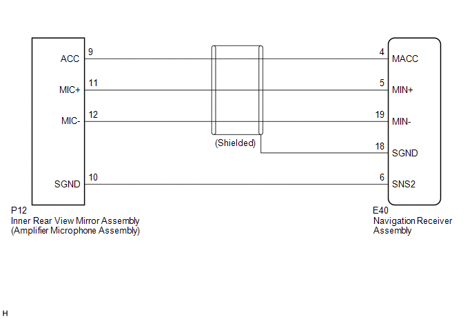
- The navigation receiver assembly and inner rear view mirror assembly (amplifier microphone assembly) are connected to each other using the microphone connection detection signal lines.
- Using this circuit, the navigation receiver assembly sends power to the inner rear view mirror assembly (amplifier microphone assembly), and the inner rear view mirror assembly (amplifier microphone assembly) sends microphone signals to the navigation receiver assembly.
WIRING DIAGRAM
PROCEDURE
|
1. |
CHECK MICROPHONE (OPERATION CHECK) |
|
(a) Enter the "Microphone Check" screen. Refer to Check Microphone in Operation Check (See page
|
|
.png)
(b) When a voice is input into the microphone, check that the microphone input level meter changes according to the input voice.
OK:
Check result is normal.
| OK | .gif) |
PROCEED TO NEXT SUSPECTED AREA SHOWN IN PROBLEM SYMPTOMS TABLE |
|
.gif)
|
2. |
CHECK HARNESS AND CONNECTOR (NAVIGATION RECEIVER ASSEMBLY - INNER REAR VIEW MIRROR ASSEMBLY (AMPLIFIER MICROPHONE ASSEMBLY)) |
(a) Disconnect the E40 navigation receiver assembly connector.
(b) Disconnect the P12 inner rear view mirror assembly (amplifier microphone assembly) connector.
(c) Measure the resistance according to the value(s) in the table below.
Standard Resistance:
|
Tester Connection |
Condition |
Specified Condition |
|---|---|---|
|
E40-4 (MACC) - P12-9 (ACC) |
Always |
Below 1 Ω |
|
E40-5 (MIN+) - P12-11 (MIC+) |
Always |
Below 1 Ω |
|
E40-19 (MIN-) - P12-12 (MIC-) |
Always |
Below 1 Ω |
|
E40-6 (SNS2) - P12-10 (SGND) |
Always |
Below 1 Ω |
|
E40-4 (MACC) - Body ground |
Always |
10 kΩ or higher |
|
E40-5 (MIN+) - Body ground |
Always |
10 kΩ or higher |
|
E40-19 (MIN-) - Body ground |
Always |
10 kΩ or higher |
|
E40-18 (SGND) - Body ground |
Always |
10 kΩ or higher |
|
E40-6 (SNS2) - Body ground |
Always |
10 kΩ or higher |
| NG | |
REPAIR OR REPLACE HARNESS OR CONNECTOR |
|
|
3. |
INSPECT NAVIGATION RECEIVER ASSEMBLY |
(a) Reconnect the E40 navigation receiver assembly connector.
(b) Reconnect the P12 inner rear view mirror assembly (amplifier microphone assembly) connector.
|
(c) Measure the voltage according to the value(s) in the table below. Standard Voltage:
|
|
(d) Measure the resistance according to the value(s) in the table below.
Standard Resistance:
|
Tester Connection |
Condition |
Specified Condition |
|---|---|---|
|
E40-18 (SGND) - Body ground |
Always |
Below 1 Ω |
|
E40-19 (MIN-) - Body ground |
Always |
Below 1 Ω |
|
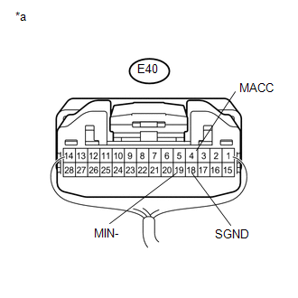
*a |
Component with harness connected (Navigation Receiver Assembly) |
| NG | |
REPLACE NAVIGATION RECEIVER ASSEMBLY |
|
|
4. |
INSPECT INNER REAR VIEW MIRROR ASSEMBLY (AMPLIFIER MICROPHONE ASSEMBLY) |
(a) Remove the inner rear view mirror assembly (amplifier microphone assembly)
(See page .gif) ).
).
|
(b) Measure the resistance according to the value(s) in the table below. Standard Resistance:
|
|
| NG | |
REPLACE INNER REAR VIEW MIRROR ASSEMBLY (AMPLIFIER MICROPHONE ASSEMBLY) |
|
|
5. |
INSPECT INNER REAR VIEW MIRROR ASSEMBLY (AMPLIFIER MICROPHONE ASSEMBLY) |
(a) Reconnect the E40 navigation receiver assembly connector.
(b) Reconnect the P12 inner rear view mirror assembly (amplifier microphone assembly) connector.
(c) Turn the ignition switch to ACC.
|
(d) Connect an oscilloscope to terminals 11 (MIC+) and 12 (MIC-) of the P12 inner rear view mirror assembly (amplifier microphone assembly) connector. |
|
.png)
(e) Check the waveform of the amplifier microphone assembly using the oscilloscope.
|
Result |
Proceed to |
|---|---|
|
A waveform synchronized with the voice input to the inner rear view mirror assembly (amplifier microphone assembly) is output |
A |
|
A waveform synchronized with the voice input to the inner rear view mirror assembly (amplifier microphone assembly) is not output |
B |
|
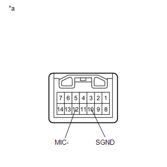
*a |
Component with harness connected (Inner Rear View Mirror Assembly (Amplifier Microphone Assembly)) |
| A | |
PROCEED TO NEXT SUSPECTED AREA SHOWN IN PROBLEM SYMPTOMS TABLE |
| B | |
REPLACE INNER REAR VIEW MIRROR ASSEMBLY (AMPLIFIER MICROPHONE ASSEMBLY) |
 Vehicle Speed Signal Circuit between Stereo Component Amplifier and Combination
Meter
Vehicle Speed Signal Circuit between Stereo Component Amplifier and Combination
Meter
DESCRIPTION
The stereo component amplifier assembly receives a vehicle speed signal from
the combination meter assembly to control the ASL function.
HINT:
A voltage of 12 V or 5 V is outp ...
 Navigation Receiver Assembly Power Source Circuit
DESCRIPTION
This is the power source circuit to operate the navigation receiver assembly.
WIRING DIAGRAM
CAUTION / NOTICE / HINT
NOTICE:
Inspect the fuses for circuits related to this system be ...
Other materials about Toyota Venza:
PIG Power Supply Voltage Malfunction (C1552)
DESCRIPTION
When a problem occurs in the power steering system, the power source relay circuit
is shut off to stop the power assist.
DTC No.
DTC Detection Condition
Trouble Area
C1552
PIG power s ...
Adjustment
ADJUSTMENT
CAUTION / NOTICE / HINT
HINT:
Centering bolts are used to mount the hood hinge and hood lock. The
hood and hood lock cannot be adjusted with the centering bolts installed.
Substitute the centering bolts with standard bolts when ...
Precaution
PRECAUTION
1. WHEN DISCONNECTING CABLE FROM NEGATIVE BATTERY TERMINAL
NOTICE:
When disconnecting the cable from the negative (-) battery terminal, initialize
the following systems after the cable is reconnected.
System Name
See Proc ...

0.1795