Toyota Venza: Navigation Receiver Assembly Communication Stop Mode
DESCRIPTION
|
Detection Item |
Symptom |
Trouble Area |
|---|---|---|
|
Navigation Receiver Assembly Communication Stop Mode |
|
|
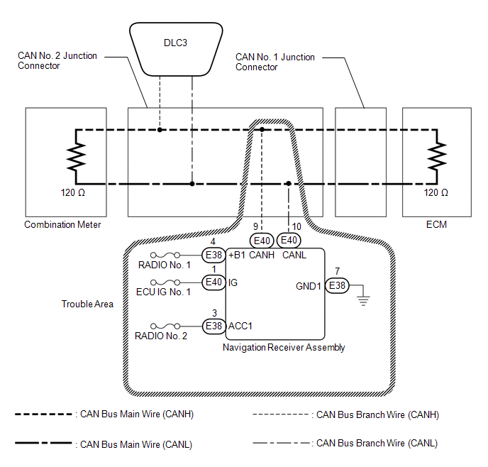
WIRING DIAGRAM
CAUTION / NOTICE / HINT
NOTICE:
- Turn the ignition switch off before measuring the resistances between CAN bus main wires and between CAN bus branch wires.
- Turn the ignition switch off before inspecting CAN bus wires for a ground short.
- After the ignition switch is turned off, check that the key reminder warning system and light reminder warning system are not operating.
- Before measuring the resistance, leave the vehicle as is for at least 1 minute and do not operate the ignition switch, any other switches or the doors. If any doors need to be opened in order to check connectors, open the doors and leave them open.
HINT:
- Operating the ignition switch, any other switches or a door triggers related ECU and sensor communication on the CAN. This communication will cause the resistance value to change.
- Even after DTCs are cleared, if a DTC is stored again after driving the vehicle for a while, the malfunction may be occurring due to vibration of the vehicle. In such a case, wiggling the ECUs or wire harness while performing the inspection below may help determine the cause of the malfunction.
PROCEDURE
|
1. |
CHECK FOR OPEN IN CAN BUS WIRES (NAVIGATION RECEIVER ASSEMBLY BRANCH WIRE) |
(a) Turn the ignition switch off.
|
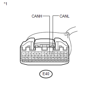
(b) Disconnect the navigation receiver assembly connector. Text in Illustration
|
|
(c) Measure the resistance according to the value(s) in the table below.
Standard Resistance:
|
Tester Connection |
Condition |
Specified Condition |
|---|---|---|
|
E40-9 (CANH) - E40-10 (CANL) |
Ignition switch off |
54 to 69 Ω |
| NG | .gif) |
REPAIR OR REPLACE CAN BUS BRANCH WIRE OR CONNECTOR (NAVIGATION RECEIVER ASSEMBLY BRANCH WIRE) |
|
.gif)
|
2. |
CHECK HARNESS AND CONNECTOR (POWER SOURCE TERMINAL) |
|
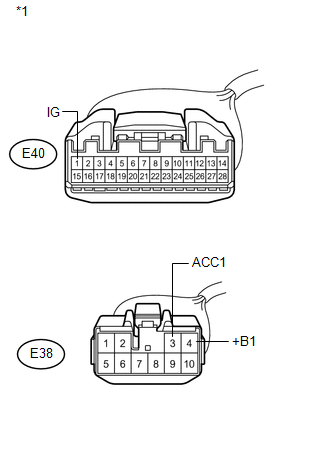
(a) Disconnect the navigation receiver assembly connector. Text in Illustration
|
|
(b) Measure the voltage according to the value(s) in the table below.
Standard Voltage:
|
Tester Connection |
Condition |
Specified Condition |
|---|---|---|
|
E38-4 (+B1) - Body ground |
Always |
11 to 14 V |
|
E38-3 (ACC1) - Body ground |
Ignition switch ACC |
11 to 14 V |
|
E40-1 (IG) - Body ground |
Ignition switch ON |
11 to 14 V |
| NG | |
REPAIR OR REPLACE HARNESS OR CONNECTOR (POWER SOURCE TERMINAL) |
|
|
3. |
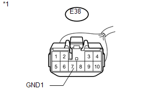
CHECK HARNESS AND CONNECTOR (GROUND TERMINAL) |
|
(a) Measure the resistance according to the value(s) in the table below. Standard Resistance:
|
|
| OK | |
REPLACE NAVIGATION RECEIVER ASSEMBLY |
| NG | |
REPAIR OR REPLACE HARNESS OR CONNECTOR (GROUND TERMINAL) |
 4WD Control ECU Communication Stop Mode
DESCRIPTION
Detection Item
Symptom
Trouble Area
4WD Control ECU Communication Stop Mode
"Four Wheel Drive Control" is ...
 Audio Receiver Assembly Communication Stop Mode
DESCRIPTION
Detection Item
Symptom
Trouble Area
Audio Receiver Assembly Communication Stop Mode
"Display and Navigation (A ...
Other materials about Toyota Venza:
Engine does not Start
DESCRIPTION
1. ENGINE START SYSTEM FUNCTION
(a) If the engine switch is pressed with the shift lever in P or N and the brake
pedal depressed, the power management control ECU determines that this is an engine
start request.
(b) The certification ECU (sm ...
Wireless-linked Return Function does not Operate
DESCRIPTION
When a door is unlocked using the wireless unlock function or entry unlock function,
the certification ECU (smart key ECU assembly) sends a door unlock signal and key
ID signal to the main body ECU (driver side junction block assembly). When t ...
Removal
REMOVAL
PROCEDURE
1. REMOVE REAR DOOR SCUFF PLATE RH
HINT:
Use the same procedure for the RH side and LH side (See page
).
2. DISCONNECT REAR DOOR OPENING TRIM WEATHERSTRIP RH
HINT:
Use the same procedure for the RH side and LH side (See page
).
3. ...

0.1281