Toyota Venza: Audio Receiver Assembly Communication Stop Mode
DESCRIPTION
|
Detection Item |
Symptom |
Trouble Area |
|---|---|---|
|
Audio Receiver Assembly Communication Stop Mode |
|
|
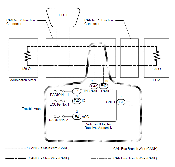
WIRING DIAGRAM
CAUTION / NOTICE / HINT
NOTICE:
- Turn the ignition switch off before measuring the resistances between CAN bus main wires and between CAN bus branch wires.
- Turn the ignition switch off before inspecting CAN bus wires for a ground short.
- After the ignition switch is turned off, check that the key reminder warning system and light reminder warning system are not operating.
- Before measuring the resistance, leave the vehicle as is for at least 1 minute and do not operate the ignition switch, any other switches or the doors. If any doors need to be opened in order to check connectors, open the doors and leave them open.
HINT:
- Operating the ignition switch, any other switches or a door triggers related ECU and sensor communication on the CAN. This communication will cause the resistance value to change.
- Even after DTCs are cleared, if a DTC is stored again after driving the vehicle for a while, the malfunction may be occurring due to vibration of the vehicle. In such a case, wiggling the ECUs or wire harness while performing the inspection below may help determine the cause of the malfunction.
PROCEDURE
|
1. |
CHECK FOR OPEN IN CAN BUS WIRES (RADIO AND DISPLAY RECEIVER ASSEMBLY BRANCH WIRE) |
(a) Turn the ignition switch off.
|
(b) Disconnect the radio and display receiver assembly connector. Text in Illustration
|
|
(c) Measure the resistance according to the value(s) in the table below.
Standard Resistance:
|
Tester Connection |
Condition |
Specified Condition |
|---|---|---|
|
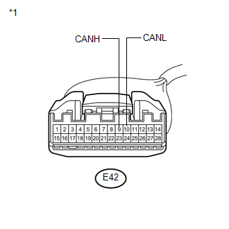
E42-9 (CANH) - E42-10 (CANL) |
Ignition switch off |
54 to 69 Ω |
| NG | .gif) |
REPAIR OR REPLACE CAN BUS BRANCH WIRE OR CONNECTOR (RADIO AND DISPLAY RECEIVER ASSEMBLY BRANCH WIRE) |
|
.gif)
|
2. |
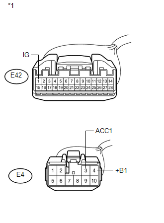
CHECK HARNESS AND CONNECTOR (POWER SOURCE TERMINAL) |
(a) Disconnect the radio and display receiver assembly connector.
|
(b) Measure the voltage according to the value(s) in the table below. Standard Voltage:
|
|
| NG | |
REPAIR OR REPLACE HARNESS OR CONNECTOR (POWER SOURCE TERMINAL) |
|
|
3. |
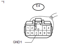
CHECK HARNESS AND CONNECTOR (GROUND TERMINAL) |
|
(a) Measure the resistance according to the value(s) in the table below. Standard Resistance:
|
|
| OK | |
REPLACE RADIO AND DISPLAY RECEIVER ASSEMBLY |
| NG | |
REPAIR OR REPLACE HARNESS OR CONNECTOR (GROUND TERMINAL) |
 Navigation Receiver Assembly Communication Stop Mode
DESCRIPTION
Detection Item
Symptom
Trouble Area
Navigation Receiver Assembly Communication Stop Mode
"Display and Navigati ...
 Open in CAN Main Bus Line
DESCRIPTION
There may be an open circuit in the CAN bus main wire and/or the DLC3 branch
wire when the resistance between terminals 6 (CANH) and 14 (CANL) of the DLC3 is
70 Ω or higher.
...
Other materials about Toyota Venza:
Luggage Compartment Room Light
Components
COMPONENTS
ILLUSTRATION
Removal
REMOVAL
PROCEDURE
1. REMOVE NO. 2 ROOM LIGHT ASSEMBLY
(a) Using a moulding remover, disengage the claw.
(b) Disconnect the connector and remove t ...
Engine
General Maintenance
GENERAL MAINTENANCE
CAUTION / NOTICE / HINT
HINT:
Perform these procedures after the engine has cooled down.
PROCEDURE
1. INSPECT DRIVE BELT
Engine Type
See Procedure
2GR-FE
See pag ...
On-vehicle Inspection
ON-VEHICLE INSPECTION
CAUTION / NOTICE / HINT
HINT:
Use the same procedure for the RH side and LH side.
The procedure listed below is for the LH side.
PROCEDURE
1. REMOVE REAR WHEEL
2. SEPARATE REAR FLEXIBLE HOSE
3. SEPARATE REAR DI ...

0.1145