Toyota Venza: LVDS Signal Malfunction (from Extension Module) (B1532)
DESCRIPTION
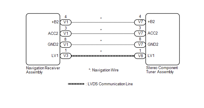
The stereo component tuner assembly and the navigation receiver assembly are connected by the LVDS communication line.
This DTC is stored when an LVDS communication error occurs between the stereo component tuner assembly and the navigation receiver assembly.
|
DTC No. |
DTC Detection Condition |
Trouble Area |
|---|---|---|
|
B1532 |
When any of the following conditions is met:
|
|
HINT:
Even if no malfunction is present, this DTC may be stored depending on the battery condition or engine start voltage.
WIRING DIAGRAM
CAUTION / NOTICE / HINT
NOTICE:
After replacing the stereo component tuner assembly of vehicles subscribed to pay-type satellite radio broadcasts, XM radio ID registration is necessary.
PROCEDURE
|
1. |
CHECK NAVIGATION WIRE (STEREO COMPONENT TUNER ASSEMBLY POWER SOURCE) |
(a) Disconnect the V7 stereo component tuner assembly connector.
(b) Measure the resistance according to the value(s) in the table below.
Standard Resistance:
|
Tester Connection |
Condition |
Specified Condition |
|---|---|---|
|
V7-8 (GND2) - Body ground |
Always |
Below 1 Ω |
(c) Measure the voltage according to the value(s) in the table below.
Standard Voltage:
|
Tester Connection |
Condition |
Specified Condition |
|---|---|---|
|
V7-4 (+B2) - V7-8 (GND2) |
Always |
11 to 14 V |
|
V7-3 (ACC2) - V7-8 (GND2) |
Ignition switch ACC |
11 to 14 V |
| NG | .gif) |
GO TO STEP 4 |
|
.gif)
|
2. |
REPLACE NAVIGATION WIRE |
(a) Replace the navigation wire with a new or known good one (See page
.gif) ).
).
(b) Clear the DTCs (See page ).
(c) Recheck for DTCs and check that no DTCs are output.
OK:
No DTCs are output.
| OK | |
END |
|
|
3. |
REPLACE STEREO COMPONENT TUNER ASSEMBLY |
(a) Replace the stereo component tuner assembly with a new or known good one
(See page ).
(b) Clear the DTCs (See page ).
(c) Recheck for DTCs and check that no DTCs are output.
OK:
No DTCs are output.
| OK | |
END |
| NG | |
REPLACE NAVIGATION RECEIVER ASSEMBLY |
|
4. |
CHECK NAVIGATION WIRE |
(a) Remove the navigation wire (See page ).
(b) Measure the resistance according to the value(s) in the table below.
Standard Resistance::
|
Tester Connection |
Condition |
Specified Condition |
|---|---|---|
|
V1-4 (+B2) - V7-4 (+B2) |
Always |
Below 1 Ω |
|
V1-3 (ACC2) - V7-3 (ACC2) |
Always |
Below 1 Ω |
|
V1-8 (GND2) - V7-8 (GND2) |
Always |
Below 1 Ω |
|
V1-4 (+B2) - Body ground |
Always |
10 kΩ or higher |
|
V1-3 (ACC2) - Body ground |
Always |
10 kΩ or higher |
|
V1-8 (GND2) - Body ground |
Always |
Below 1 Ω |
| OK | |
REPLACE NAVIGATION RECEIVER ASSEMBLY |
| NG | |
REPLACE NAVIGATION WIRE |
 Diagnostic Trouble Code Chart
DIAGNOSTIC TROUBLE CODE CHART
Navigation System
DTC Code
Detection Item
See page
B1532
LVDS Signal Malfunction (from Extension Module)
...
 Voice Recognition Microphone Disconnected (B1579)
DESCRIPTION
The navigation receiver assembly and inner rear view mirror assembly (amplifier
microphone assembly) are connected to each other using the microphone connection
detection signal lines ...
Other materials about Toyota Venza:
Gauges and meters
►Vehicles with smart key system
The following gauges, meters and display illuminate when the “ENGINE START STOP”
switch is in IGNITION ON mode.
►Vehicles without smart key system
The following gauges, meters and displays illuminate when ...
Fuel Injector Circuit
DESCRIPTION
The fuel injector assemblies are located on the intake manifold. They inject
fuel into the cylinders based on signals from the ECM.
WIRING DIAGRAM
CAUTION / NOTICE / HINT
NOTICE:
Inspect the fuses for circuits related to this system befo ...
Entry Interior Alarm does not Sound
DESCRIPTION
The smart key system uses the combination meter buzzer to perform various vehicle
interior warnings. When the conditions for each warning are met, the certification
ECU (smart key ECU assembly) sends a buzzer signal to the combination meter as ...

0.1413