Toyota Venza: Removal
REMOVAL
PROCEDURE
1. REMOVE REAR SEAT HEADREST ASSEMBLY
.gif)
2. REMOVE REAR SEAT CENTER HEADREST ASSEMBLY
3. REMOVE REAR SEAT INNER TRACK BRACKET COVER
4. REMOVE REAR SEAT OUTER TRACK BRACKET COVER
5. DISCONNECT REAR SEAT RECLINING CONTROL CABLE SUB-ASSEMBLY
6. REMOVE REAR SEAT ASSEMBLY RH
7. REMOVE SEAT ADJUSTER COVER CAP RH
8. REMOVE REAR SEAT RECLINING RELEASE LEVER RH
9. REMOVE REAR SEAT RECLINING COVER RH
10. REMOVE CENTER SEAT HINGE COVER RH
11. REMOVE REAR SEAT INNER RECLINING COVER RH
12. REMOVE REAR SEAT CENTER ARMREST ASSEMBLY
13. REMOVE REAR SEAT CUSHION COVER WITH PAD
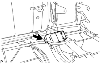
14. REMOVE REAR SEAT INNER BELT ASSEMBLY RH
|
(a) Remove the bolt and the rear seat inner belt assembly RH. |
|
 Components
COMPONENTS
ILLUSTRATION
ILLUSTRATION
...
 Installation
INSTALLATION
PROCEDURE
1. INSTALL REAR SEAT INNER BELT ASSEMBLY RH
(a) Install the rear seat inner belt assembly RH with the bolt.
Torque:
42 N·m {428 kgf·cm, 31 ft·lbf}
...
Other materials about Toyota Venza:
Cruise Control Main Switch
Components
COMPONENTS
ILLUSTRATION
Removal
REMOVAL
PROCEDURE
1. REMOVE STEERING PAD
(See page )
2. REMOVE CRUISE CONTROL MAIN SWITCH
(a) Remove the 2 screws.
(b) Disconnect t ...
Off-road driving
Your vehicle is not designed to be driven off-road. However, in the event that
off-road driving cannot be avoided, please observe the following precautions to
help avoid the areas prohibited to vehicles.
• Drive your vehicle only in areas where off-road ...
Problem Symptoms Table
PROBLEM SYMPTOMS TABLE
HINT:
Use the table below to help determine the cause of problem symptoms.
If multiple suspected areas are listed, the potential causes of the symptoms
are listed in order of probability in the "Suspected Area" ...

0.1359