Toyota Venza: Low Power Supply Voltage (C1241/94)
DESCRIPTION
If a malfunction in the power source circuit occurs, or a malfunction in communication with the skid control ECU or in a speed sensor occurs, the AWD control ECU will prohibit operations by the fail-safe function.
|
DTC No. |
DTC Detection Condition |
Trouble Area |
|---|---|---|
|
C1241/94 |
|
|
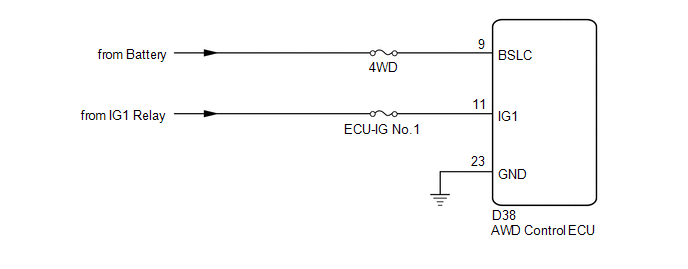
WIRING DIAGRAM
CAUTION / NOTICE / HINT
NOTICE:
Inspect the fuses for circuits related to this system before performing the following inspection procedure.
HINT:
Check the condition of each related circuit connector before troubleshooting
(See page .gif) ).
).
PROCEDURE
|
1. |
CHECK FOR DTC (CAN COMMUNICATION SYSTEM AND BRAKE CONTROL SYSTEM) |
(a) Check if the CAN communication system DTC is output (See page
).
(b) Start the engine.
(c) Drive the vehicle, accelerate to a speed of 3 km/h (2 mph) or more, and check
if the speed sensor DTC (brake control system DTC) is output (See page
).
|
Result |
Proceed to |
|---|---|
|
Neither CAN communication system DTC nor speed sensor DTC (brake control system DTC) is output |
A |
|
CAN communication system DTC is output |
B |
|
Speed sensor DTC (brake control system DTC) is output |
C |
| B | .gif) |
REPAIR CIRCUIT INDICATOR BY OUTPUT CODE (CAN COMMUNICATION SYSTEM) |
| C | |
REPAIR CIRCUIT INDICATOR BY OUTPUT CODE (BRAKE CONTROL SYSTEM) |
|
.gif)
|
2. |
INSPECT BATTERY |
(a) Check the battery voltage.
Standard Voltage:
11 to 14 V
|
Result |
Proceed to |
|---|---|
|
OK |
A |
|
NG (2GR-FE) |
B |
|
NG (1AR-FE) |
C |
| B | |
INSPECT CHARGING SYSTEM (2GR-FE) |
| C | |
INSPECT CHARGING SYSTEM (1AR-FE) |
|
|
3. |
CHECK WIRE HARNESS (AWD CONTROL ECU - BATTERY) |
(a) Disconnect the ECU connector.
(b) Measure the voltage of the wire harness side connector.
Standard Voltage:
|
Tester Connection |
Switch Condition |
Specified Condition |
|---|---|---|
|
D38-11 (IG1) - Body Ground |
Ignition switch ON |
11 to 14 V |
|
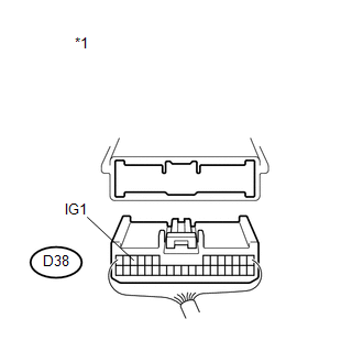
*1 |
Rear view of wire harness connector (to AWD Control ECU) |
| NG | |
REPAIR OR REPLACE HARNESS OR CONNECTOR |
|
|
4. |
CHECK WIRE HARNESS (AWD CONTROL ECU - BODY GROUND) |
(a) Disconnect the ECU connector.
(b) Measure the resistance of the wire harness side connector.
Standard Resistance:
|
Tester Connection |
Condition |
Specified Condition |
|---|---|---|
|
D38-23 (GND) - Body Ground |
Always |
Below 1 Ω |
|
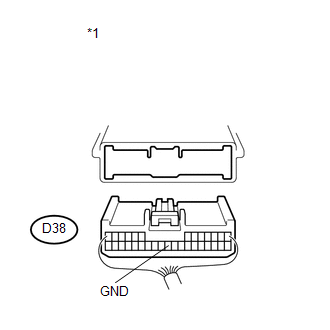
*1 |
Rear view of wire harness connector (to AWD Control ECU) |
| NG | |
REPAIR OR REPLACE HARNESS OR CONNECTOR |
|
|
5. |
RECONFIRM DTC |
(a) Clear the DTC (See page ).
(b) Start the engine.
(c) Drive the vehicle, accelerate to a speed of 3 km/h (2 mph or more, and check if the same DTC is output.
|
Result |
Proceed to |
|---|---|
|
DTC is output |
A |
|
DTC is not output |
B |
HINT:
Reinstall the sensor, connectors, etc. and restore the vehicle to its prior condition before rechecking DTCs.
| A | |
REPLACE AWD CONTROL ECU |
| B | |
CHECK INTERMITTENT PROBLEMS |
 Diagnostic Trouble Code Chart
DIAGNOSTIC TROUBLE CODE CHART
ACTIVE TORQUE CONTROL 4WD SYSTEM
DTC Code
Detection Item
Trouble Area
See page
C1241/94
Low Powe ...
 Control Module Communication Bus OFF (U0073/86,U0100/85,U0129/83)
DESCRIPTION
The AWD control ECU inputs the signals sent from the ECM and skid control
ECU via the CAN communication system.
When DTCs indicating a CAN communication system malfunction ...
Other materials about Toyota Venza:
Removal
REMOVAL
PROCEDURE
1. PRECAUTION
CAUTION:
Be sure to read Precaution thoroughly before servicing (See page
).
2. DISCONNECT CABLE FROM NEGATIVE BATTERY TERMINAL
CAUTION:
Wait at least 90 seconds after disconnecting the cable from the negative (-)
bat ...
Transmitter ID not Received in Main Mode (C2126/26)
DESCRIPTION
After all IDs are registered, DTC C2126/26 is set in the tire pressure warning
ECU and the tire pressure warning light blinks for 1 minute and then comes on.
When the tire pressure warning ECU successfully receives radio waves from all
the tr ...
Diagnostic Trouble Code Chart
DIAGNOSTIC TROUBLE CODE CHART
Sliding Roof (Sliding Roof ECU (Sliding Roof Drive Gear Sub-assembly))
DTC Code
Detection Item
Trouble Area
See page
B2341
Sensor (Motor) Failure
...

0.1217