Toyota Venza: Radio Antenna
Components
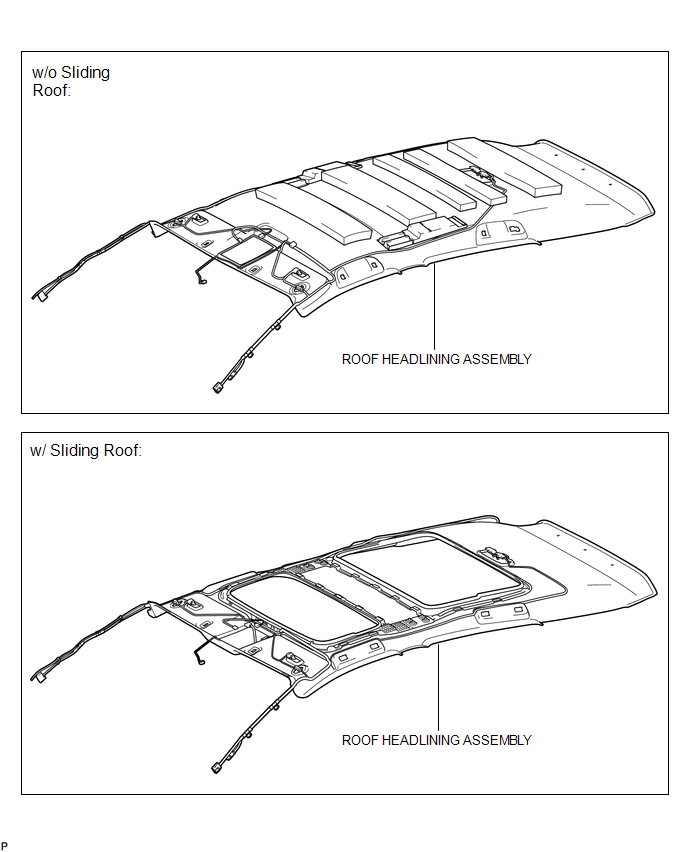
COMPONENTS
ILLUSTRATION
ILLUSTRATION
Installation
INSTALLATION
PROCEDURE
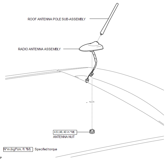
1. INSTALL RADIO ANTENNA ASSEMBLY
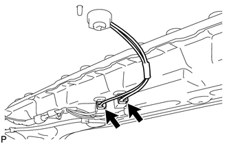
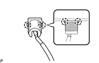
(a) Engage the 2 claws to install the radio antenna assembly.
|
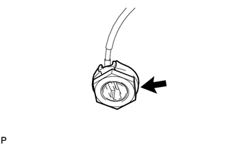
(b) Place the antenna cord in the cutout of the antenna nut. Text in Illustration
|
|

(c) Install the radio antenna assembly with the antenna nut.
Torque:
4.5 N·m {46 kgf·cm, 40 in·lbf}
(d) Connect the 2 connectors.
2. INSTALL ROOF ANTENNA POLE SUB-ASSEMBLY
3. INSTALL ROOF HEADLINING ASSEMBLY
(See page .gif) )
)
Removal
REMOVAL
PROCEDURE
1. REMOVE ROOF HEADLINING ASSEMBLY
(See page .gif) )
)
2. REMOVE ROOF ANTENNA POLE SUB-ASSEMBLY
3. REMOVE RADIO ANTENNA ASSEMBLY
|
(a) Disconnect the 2 connectors. |
|
|
(b) Remove the antenna nut. |
|
|
(c) Disengage the 2 claws and remove the radio antenna assembly. |
|
 Microphone
Components
COMPONENTS
ILLUSTRATION
Removal
REMOVAL
PROCEDURE
1. REMOVE INNER REAR VIEW MIRROR STAY HOLDER COVER
2. REMOVE TELEPHONE MICROPHONE ASSEMBLY (INNER REAR VIEW MIRROR ASSEMBLY ...

Other materials about Toyota Venza:
Installation
INSTALLATION
PROCEDURE
1. INSTALL FRONT NO. 3 SPEAKER ASSEMBLY (for 13 Speakers)
(a) Engage the 3 claws to install the front No. 3 speaker assembly.
2. INSTALL FRONT PILLAR GARNISH CORNER PIECE (for ...
Installation
INSTALLATION
PROCEDURE
1. INSTALL WATER PUMP ASSEMBLY
(a) Install a new gasket and the water pump with the 7 bolts.
Torque:
21 N·m {214 kgf·cm, 15 ft·lbf}
2. INSTALL V-RIBBED BELT TENSIONE ...
Problem Symptoms Table
PROBLEM SYMPTOMS TABLE
HINT:
Use the table below to help determine the cause of problem symptoms. If multiple
suspected areas are listed, the potential causes of the symptoms are listed in order
of probability in the "Suspected Area" column of ...

0.1322