Toyota Venza: Lost Communication with Rear Airbag Sensor RH (B1632/81,B1633/81,B1642/81,B1692/81,B1693/81)
DESCRIPTION
The side collision sensor RH circuit (to determine deployment of the front seat side airbag assembly RH and curtain shield airbag assembly RH) is composed of the center airbag sensor assembly, rear airbag sensor RH and side airbag sensor RH.
The rear airbag sensor RH and side airbag sensor RH detect impacts to the vehicle and send signals to the center airbag sensor assembly to determine if the airbag should be deployed.
These DTCs are stored when a malfunction is detected in the circuit for the side collision sensor RH (to determine deployment of the front seat side airbag assembly RH and curtain shield airbag assembly RH).
|
DTC No. |
DTC Detection Condition |
Trouble Area |
|---|---|---|
|
B1632/81 B1633/81 B1642/81 B1692/81 B1693/81 |
|
|
WIRING DIAGRAM
.png)
PROCEDURE
|
1. |
CHECK CURRENT DTC |
(a) Turn the ignition switch to ON, and wait for at least 60 seconds.
(b) Check the current DTCs (See page .gif) ).
).
|
Result |
Proceed to |
|---|---|
|
Current DTC B1633 is output. |
A |
|
Current DTC B1642 or 81 is output. |
B |
|
Current DTC B1692 or B1693 is output. |
C |
|
Current DTC B1632 is output. |
D |
|
Current DTC B1632, B1633, B1642, B1692, B1693 or 81 is not output. |
E |
HINT:
- DTCs indicating communication errors will be changed to DTCs indicating errors in initialization by turning the ignition switch off and then to ON again.
- Codes other than current DTCs B1632, B1633, B1642, B1692, B1693 and 81 may be output at this time, but they are not related to this check.
| B | .gif) |
GO TO STEP 3 |
| C | |
GO TO STEP 14 |
| D | |
GO TO STEP 21 |
| E | |
USE SIMULATION METHOD TO CHECK |
|
.gif)
|
2. |
CHECK HISTORY DTC |
(a) Turn the ignition switch to ON, and wait for at least 60 seconds.
(b) Check the history DTCs (See page ).
|
Result |
Proceed to |
|---|---|
|
History DTC B1632 is not output. |
A |
|
History DTC B1632 is output. |
B |
HINT:
Codes other than history DTC B1632 may be output at this time, but they are not related to this check.
| B | |
GO TO STEP 21 |
|
|
3. |
CHECK CONNECTORS |
(a) Turn the ignition switch off.
(b) Disconnect the cable from the negative (-) battery terminal, and wait for at least 90 seconds.
(c) Check that the connectors are properly connected to the center airbag sensor assembly, rear airbag sensor RH and side airbag sensor RH. Also check that the connectors that link the No. 2 floor wire and front door wire RH are properly connected.
OK:
The connectors are properly connected.
HINT:
If the connectors are not connected securely, reconnect the connectors and proceed to the next inspection.
(d) Disconnect the connectors from the center airbag sensor assembly, rear airbag sensor RH and side airbag sensor RH. Also disconnect the connectors that link the No. 2 floor wire and front door wire RH.
(e) Check that the terminals of connectors are not damaged.
OK:
The terminals are not deformed or damaged.
| NG | |
REPLACE WIRE HARNESS |
|
|
4. |
CHECK NO. 2 FLOOR WIRE (OPEN) |
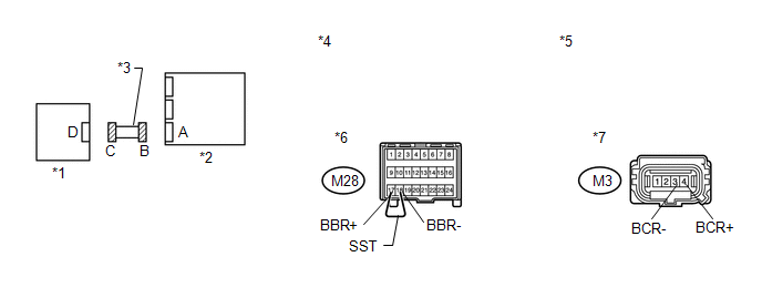
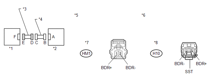
(a) Using SST, connect terminals 17 (BBR+) and 18 (BBR-) of connector B.
NOTICE:
Do not forcibly insert SST into the terminals of the connector when connecting.
SST: 09843-18040
(b) Measure the resistance according to the value(s) in the table below.
Standard Resistance:
|
Tester Connection |
Condition |
Specified Condition |
|---|---|---|
|
M3-4 (BCR+) - M3-3 (BCR-) |
Always |
Below 1 Ω |
|
*1 |
Rear Airbag Sensor RH |
*2 |
Center Airbag Sensor Assembly |
|
*3 |
No. 2 Floor Wire |
*4 |
Front view of wire harness connector (to Center Airbag Sensor Assembly) |
|
*5 |
Front view of wire harness connector (to Rear Airbag Sensor RH) |
*6 |
Connector B |
|
*7 |
Connector C |
- |
- |
| NG | |
REPLACE NO. 2 FLOOR WIRE |
|
|
5. |
CHECK NO. 2 FLOOR WIRE (SHORT) |
|
(a) Disconnect SST from connector B. |
|
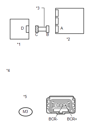
(b) Measure the resistance according to the value(s) in the table below.
Standard Resistance:
|
Tester Connection |
Condition |
Specified Condition |
|---|---|---|
|
M3-4 (BCR+) - M3-3 (BCR-) |
Always |
1 MΩ or higher |
|
*1 |
Rear Airbag Sensor RH |
|
*2 |
Center Airbag Sensor Assembly |
|
*3 |
No. 2 Floor Wire |
|
*4 |
Front view of wire harness connector (to Rear Airbag Sensor RH) |
|
*5 |
Connector C |
| NG | |
REPLACE NO. 2 FLOOR WIRE |
|
|
6. |
CHECK NO. 2 FLOOR WIRE (SHORT TO B+) |
|
(a) Connect the cable to the negative (-) battery terminal. |
|
(b) Turn the ignition switch to ON.
(c) Measure the voltage according to the value(s) in the table below.
Standard Voltage:
|
Tester Connection |
Switch Condition |
Specified Condition |
|---|---|---|
|
M3-4 (BCR+) - Body ground |
Ignition switch ON |
Below 1 V |
|
M3-3 (BCR-) - Body ground |
Ignition switch ON |
Below 1 V |
|
*1 |
Rear Airbag Sensor RH |
|
*2 |
Center Airbag Sensor Assembly |
|
*3 |
No. 2 Floor Wire |
|
*4 |
Front view of wire harness connector (to Rear Airbag Sensor RH) |
|
*5 |
Connector C |
| NG | |
REPLACE NO. 2 FLOOR WIRE |
|
|
7. |
CHECK NO. 2 FLOOR WIRE (SHORT TO GROUND) |
|
(a) Turn the ignition switch off. |
|
(b) Disconnect the cable from the negative (-) battery terminal, and wait for at least 90 seconds.
(c) Measure the resistance according to the value(s) in the table below.
Standard Resistance:
|
Tester Connection |
Condition |
Specified Condition |
|---|---|---|
|
M3-4 (BCR+) - Body ground |
Always |
1 MΩ or higher |
|
M3-3 (BCR-) - Body ground |
Always |
1 MΩ or higher |
|
*1 |
Rear Airbag Sensor RH |
|
*2 |
Center Airbag Sensor Assembly |
|
*3 |
No. 2 Floor Wire |
|
*4 |
Front view of wire harness connector (to Rear Airbag Sensor RH) |
|
*5 |
Connector C |
| NG | |
REPLACE NO. 2 FLOOR WIRE |
|
|
8. |
CHECK WIRE HARNESS (OPEN) |
(a) Connect the connectors that link the No. 2 floor wire and front door wire RH.
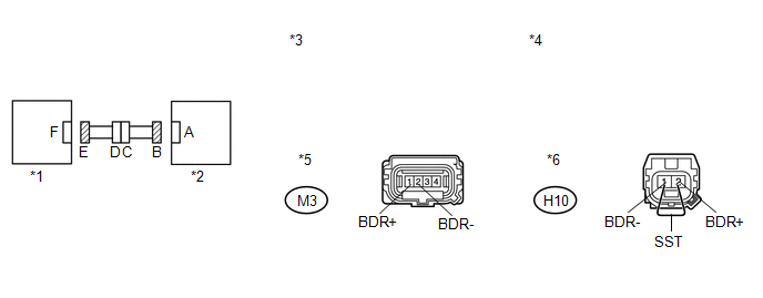
(b) Using SST, connect terminals 2 (BDR+) and 1 (BDR-) of connector E.
NOTICE:
Do not forcibly insert SST into the terminals of the connector when connecting.
SST: 09843-18040
(c) Measure the resistance according to the value(s) in the table below.
Standard Resistance:
|
Tester Connection |
Condition |
Specified Condition |
|---|---|---|
|
M3-1 (BDR+) - M3-2 (BDR-) |
Always |
Below 1 Ω |
|
*1 |
Side Airbag Sensor RH |
*2 |
Rear Airbag Sensor RH |
|
*3 |
Front view of wire harness connector (to Rear Airbag Sensor RH) |
*4 |
Front view of wire harness connector (to Side Airbag Sensor RH) |
|
*5 |
Connector B |
*6 |
Connector E |
| NG | |
GO TO STEP 22 |
|
|
9. |
CHECK WIRE HARNESS (SHORT) |
|
(a) Disconnect SST from connector E. |
|
(b) Measure the resistance according to the value(s) in the table below.
Standard Resistance:
|
Tester Connection |
Condition |
Specified Condition |
|---|---|---|
|
M3-1 (BDR+) - M3-2 (BDR-) |
Always |
1 MΩ or higher |
|
*1 |
Side Airbag Sensor RH |
|
*2 |
Rear Airbag Sensor RH |
|
*3 |
Front view of wire harness connector (to Rear Airbag Sensor RH) |
|
*4 |
Connector B |
| NG | |
GO TO STEP 23 |
|
|
10. |
CHECK WIRE HARNESS (SHORT TO B+) |
|
(a) Connect the cable to the negative (-) battery terminal. |
|
(b) Turn the ignition switch to ON.
(c) Measure the voltage according to the value(s) in the table below.
Standard Voltage:
|
Tester Connection |
Switch Condition |
Specified Condition |
|---|---|---|
|
M3-1 (BDR+) - Body ground |
Ignition switch ON |
Below 1 V |
|
M3-2 (BDR-) - Body ground |
Ignition switch ON |
Below 1 V |
|
*1 |
Side Airbag Sensor RH |
|
*2 |
Rear Airbag Sensor RH |
|
*3 |
Front view of wire harness connector (to Rear Airbag Sensor RH) |
|
*4 |
Connector B |
| NG | |
GO TO STEP 24 |
|
|
11. |
CHECK WIRE HARNESS (SHORT TO GROUND) |
|
(a) Turn the ignition switch off. |
|
(b) Disconnect the cable from the negative (-) battery terminal, and wait for at least 90 seconds.
(c) Measure the resistance according to the value(s) in the table below.
Standard Resistance:
|
Tester Connection |
Condition |
Specified Condition |
|---|---|---|
|
M3-1 (BDR+) - Body ground |
Always |
1 MΩ or higher |
|
M3-2 (BDR-) - Body ground |
Always |
1 MΩ or higher |
|
*1 |
Side Airbag Sensor RH |
|
*2 |
Rear Airbag Sensor RH |
|
*3 |
Front view of wire harness connector (to Rear Airbag Sensor RH) |
|
*4 |
Connector B |
| NG | |
GO TO STEP 25 |
|
|
12. |
CHECK REAR AIRBAG SENSOR RH |
|
(a) Turn the ignition switch off. |
|
(b) Disconnect the cable from the negative (-) battery terminal, and wait for at least 90 seconds.
(c) Interchange the rear airbag sensor LH with RH and connect the connectors to them.
(d) Connect the cable to the negative (-) battery terminal.
(e) Turn the ignition switch to ON, and wait for at least 60 seconds.
(f) Clear the DTCs stored in memory (See page
).
(g) Turn the ignition switch off.
(h) Turn the ignition switch to ON, and wait for at least 60 seconds.
(i) Check for DTCs (See page ).
|
Result |
Proceed to |
|---|---|
|
DTC B1633, B1642, or 81 is output. |
A |
|
DTC B1638, B1647, or 82 is output. |
B |
|
DTCs B1633, B1642, or 81 and B1638, B1647, or 82 are not output. |
C |
|
*1 |
Rear Airbag Sensor LH |
|
*2 |
Center Airbag Sensor Assembly |
HINT:
Codes other than DTCs B1633, B1642 or 81 and B1638, B1647 or 82 may be output at this time, but they are not related to this check.
| B | |
REPLACE REAR AIRBAG SENSOR RH |
| C | |
USE SIMULATION METHOD TO CHECK |
|
|
13. |
CHECK SIDE AIRBAG SENSOR RH |
|
(a) Turn the ignition switch off. |
|
.png)
(b) Disconnect the cable from the negative (-) battery terminal, and wait for at least 90 seconds.
(c) Return the rear airbag sensor LH and RH to their original positions and connect the connectors.
(d) Interchange the side airbag sensor LH with RH and connect the connectors.
(e) Connect the cable to the negative (-) battery terminal.
(f) Turn the ignition switch to ON, and wait for at least 60 seconds.
(g) Clear the DTCs stored in memory (See page
).
(h) Turn the ignition switch off.
(i) Turn the ignition switch to ON, and wait for at least 60 seconds.
(j) Check for DTCs (See page ).
|
Result |
Proceed to |
|---|---|
|
DTCs B1633, B1642, or 81 and B1638, B1647, or 82 are not output. |
A |
|
DTC B1638, B1647, or 82 is output. |
B |
|
DTC B1633, B1642, or 81 is output. |
C |
|
*1 |
Side Airbag Sensor LH |
|
*2 |
Rear Airbag Sensor RH |
HINT:
Codes other than DTC B1633, B1642 or 81 and B1638, B1647 or 82 may be output at this time, but they are not related to this check.
| A | |
USE SIMULATION METHOD TO CHECK |
| B | |
REPLACE SIDE AIRBAG SENSOR RH |
| C | |
REPLACE CENTER AIRBAG SENSOR ASSEMBLY |
|
14. |
CHECK CONNECTORS |
(a) Turn the ignition switch off.
(b) Disconnect the cable from the negative (-) battery terminal, and wait for at least 90 seconds.
(c) Check that the connectors are properly connected to the rear airbag sensor RH and side airbag sensor RH. Also check that the connectors that link the No. 2 floor wire and front door wire RH are properly connected.
OK:
The connectors are properly connected.
HINT:
If the connectors are not connected securely, reconnect the connectors and proceed to the next inspection.
(d) Disconnect the connectors from the rear airbag sensor RH and side airbag sensor RH. Also disconnect the connectors that link the No. 2 floor wire and front door wire RH.
(e) Check that the terminals of connectors are not damaged.
OK:
The terminals are not deformed or damaged.
| NG | |
REPLACE WIRE HARNESS |
|
|
15. |
CHECK WIRE HARNESS (OPEN) |
(a) Connect the connectors that link the No. 2 floor wire and front door wire RH.
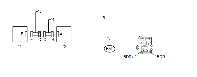
(b) Using SST, connect terminals 2 (BDR+) and 1 (BDR-) of connector E.
NOTICE:
Do not forcibly insert SST into the terminals of the connector when connecting.
SST: 09843-18040
(c) Measure the resistance according to the value(s) in the table below.
Standard Resistance:
|
Tester Connection |
Condition |
Specified Condition |
|---|---|---|
|
M3-1 (BDR+) - M3-2 (BDR-) |
Always |
Below 1 Ω |
|
*1 |
Side Airbag Sensor RH |
*2 |
Rear Airbag Sensor RH |
|
*3 |
Front view of wire harness connector (to Rear Airbag Sensor RH) |
*4 |
Front view of wire harness connector (to Side Airbag Sensor RH) |
|
*5 |
Connector B |
*6 |
Connector E |
| NG | |
GO TO STEP 22 |
|
|
16. |
CHECK WIRE HARNESS (SHORT) |
|
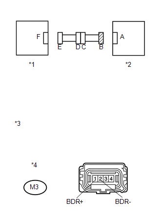
(a) Disconnect SST from connector E. |
|
(b) Measure the resistance according to the value(s) in the table below.
Standard Resistance:
|
Tester Connection |
Condition |
Specified Condition |
|---|---|---|
|
M3-1 (BDR+) - M3-2 (BDR-) |
Always |
1 MΩ or higher |
|
*1 |
Side Airbag Sensor RH |
|
*2 |
Rear Airbag Sensor RH |
|
*3 |
Front view of wire harness connector (to Rear Airbag Sensor RH) |
|
*4 |
Connector B |
| NG | |
GO TO STEP 23 |
|
|
17. |
CHECK WIRE HARNESS (SHORT TO B+) |
|
(a) Connect the cable to the negative (-) battery terminal. |
|
(b) Turn the ignition switch to ON.
(c) Measure the voltage according to the value(s) in the table below.
Standard Voltage:
|
Tester Connection |
Switch Condition |
Specified Condition |
|---|---|---|
|
M3-1 (BDR+) - Body ground |
Ignition switch ON |
Below 1 V |
|
M3-2 (BDR-) - Body ground |
Ignition switch ON |
Below 1 V |
|
*1 |
Side Airbag Sensor RH |
|
*2 |
Rear Airbag Sensor RH |
|
*3 |
Front view of wire harness connector (to Rear Airbag Sensor RH) |
|
*4 |
Connector B |
| NG | |
GO TO STEP 24 |
|
|
18. |
CHECK WIRE HARNESS (SHORT TO GROUND) |
|
(a) Turn the ignition switch off. |
|
(b) Disconnect the cable from the negative (-) battery terminal, and wait for at least 90 seconds.
(c) Measure the resistance according to the value(s) in the table below.
Standard Resistance:
|
Tester Connection |
Condition |
Specified Condition |
|---|---|---|
|
M3-1 (BDR+) - Body ground |
Always |
1 MΩ or higher |
|
M3-2 (BDR-) - Body ground |
Always |
1 MΩ or higher |
|
*1 |
Side Airbag Sensor RH |
|
*2 |
Rear Airbag Sensor RH |
|
*3 |
Front view of wire harness connector (to Rear Airbag Sensor RH) |
|
*4 |
Connector B |
| NG | |
GO TO STEP 25 |
|
|
19. |
CHECK SIDE AIRBAG SENSOR RH |
|
(a) Turn the ignition switch off. |
|
(b) Disconnect the cable from the negative (-) battery terminal, and wait for at least 90 seconds.
(c) Interchange the side airbag sensor LH with RH and connect the connectors.
(d) Connect the cable to the negative (-) battery terminal.
(e) Turn the ignition switch to ON, and wait for at least 60 seconds.
(f) Clear the DTCs stored in memory (See page
).
(g) Turn the ignition switch off.
(h) Turn the ignition switch to ON, and wait for at least 60 seconds.
(i) Check for DTCs (See page ).
|
Result |
Proceed to |
|---|---|
|
DTC B1692 or B1693 is output. |
A |
|
DTC B1697 or B1698 is output. |
B |
|
DTCs B1692 or B1693 and B1697 or B1698 are not output. |
C |
|
*1 |
Side Airbag Sensor LH |
|
*2 |
Rear Airbag Sensor RH |
HINT:
Codes other than DTCs B1692, B1693, B1697 and B1698 may be output at this time, but they are not related to this check.
| B | |
REPLACE SIDE AIRBAG SENSOR RH |
| C | |
USE SIMULATION METHOD TO CHECK |
|
|
20. |
CHECK REAR AIRBAG SENSOR RH |
|
(a) Turn the ignition switch off. |
|
(b) Disconnect the cable from the negative (-) battery terminal, and wait for at least 90 seconds.
(c) Return the side airbag sensor LH and RH to their original positions and connect the connectors.
(d) Interchange the rear airbag sensor LH with RH and connect the connectors to them.
(e) Connect the cable to the negative (-) battery terminal.
(f) Turn the ignition switch to ON, and wait for at least 60 seconds.
(g) Clear the DTCs stored in memory (See page
).
(h) Turn the ignition switch off.
(i) Turn the ignition switch to ON, and wait for at least 60 seconds.
(j) Check for DTCs (See page ).
|
Result |
Proceed to |
|---|---|
|
DTCs B1692 or B1693 and B1697 or B1698 are not output. |
A |
|
DTC B1697 or B1698 is output. |
B |
|
DTC B1692 or B1693 is output. |
C |
|
*1 |
Rear Airbag Sensor LH |
|
*2 |
Center Airbag Sensor Assembly |
HINT:
Codes other than DTCs B1692, B1693, B1697 and B1698 may be output at this time, but they are not related to this check.
| A | |
USE SIMULATION METHOD TO CHECK |
| B | |
REPLACE REAR AIRBAG SENSOR RH |
| C | |
REPLACE CENTER AIRBAG SENSOR ASSEMBLY |
|
21. |
CHECK REAR AIRBAG SENSOR RH |
|
(a) Turn the ignition switch off. |
|
(b) Disconnect the cable from the negative (-) battery terminal, and wait for at least 90 seconds.
(c) Interchange the rear airbag sensor LH with RH and connect the connectors to them.
(d) Connect the cable to the negative (-) battery terminal.
(e) Turn the ignition switch to ON, and wait for at least 60 seconds.
(f) Clear the DTCs stored in memory (See page
).
(g) Turn the ignition switch off.
(h) Turn the ignition switch to ON, and wait for at least 60 seconds.
(i) Check for DTCs (See page ).
|
Result |
Proceed to |
|---|---|
|
DTCs B1632 and B1637 are not output. |
A |
|
DTC B1637 is output. |
B |
|
DTC B1632 is output. |
C |
|
*1 |
Rear Airbag Sensor LH |
|
*2 |
Center Airbag Sensor Assembly |
HINT:
Codes other than DTCs B1632 and B1637 may be output at this time, but they are not related to this check.
| A | |
USE SIMULATION METHOD TO CHECK |
| B | |
REPLACE REAR AIRBAG SENSOR RH |
| C | |
REPLACE CENTER AIRBAG SENSOR ASSEMBLY |
|
22. |
CHECK FRONT DOOR WIRE RH (OPEN) |
(a) Disconnect the front door wire RH connector from the No. 2 floor wire.
HINT:
SST has already been inserted into connector E.
(b) Measure the resistance according to the value(s) in the table below.
Standard Resistance:
|
Tester Connection |
Condition |
Specified Condition |
|---|---|---|
|
HM1-1 (BDR+) - HM1-2 (BDR-) |
Always |
Below 1 Ω |
|
*1 |
Side Airbag Sensor RH |
*2 |
Rear Airbag Sensor RH |
|
*3 |
Front Door Wire RH |
*4 |
No. 2 Floor Wire |
|
*5 |
Front view of wire harness connector (to No. 2 Floor Wire) |
*6 |
Front view of wire harness connector (to Side Airbag Sensor RH) |
|
*7 |
Connector D |
*8 |
Connector E |
| OK | |
REPLACE NO. 2 FLOOR WIRE |
| NG | |
REPLACE FRONT DOOR WIRE RH |
|
23. |
CHECK FRONT DOOR WIRE RH (SHORT) |
(a) Disconnect the front door wire RH connector from the No. 2 floor wire.
(b) Measure the resistance according to the value(s) in the table below.
Standard Resistance:
|
Tester Connection |
Condition |
Specified Condition |
|---|---|---|
|
HM1-1 (BDR+) - HM1-2 (BDR-) |
Always |
1 MΩ or higher |
|
*1 |
Side Airbag Sensor RH |
*2 |
Rear Airbag Sensor RH |
|
*3 |
Front Door Wire RH |
*4 |
No. 2 Floor Wire |
|
*5 |
Front view of wire harness connector (to No. 2 Floor Wire) |
*6 |
Connector D |
| OK | |
REPLACE NO. 2 FLOOR WIRE |
| NG | |
REPLACE FRONT DOOR WIRE RH |
|
24. |
CHECK FRONT DOOR WIRE RH (SHORT TO B+) |
(a) Turn the ignition switch off.
(b) Disconnect the cable from the negative (-) battery terminal, and wait for at least 90 seconds.
(c) Disconnect the front door wire RH connector from the No. 2 floor wire.
(d) Connect the cable to the negative (-) battery terminal.
(e) Turn the ignition switch to ON.
(f) Measure the voltage according to the value(s) in the table below.
Standard Voltage:
|
Tester Connection |
Switch Condition |
Specified Condition |
|---|---|---|
|
HM1-1 (BDR+) - Body ground |
Ignition switch ON |
Below 1 V |
|
HM1-2 (BDR-) - Body ground |
Ignition switch ON |
Below 1 V |
|
*1 |
Side Airbag Sensor RH |
*2 |
Rear Airbag Sensor RH |
|
*3 |
Front Door Wire RH |
*4 |
No. 2 Floor Wire |
|
*5 |
Front view of wire harness connector (to No. 2 Floor Wire) |
*6 |
Connector D |
| OK | |
REPLACE NO. 2 FLOOR WIRE |
| NG | |
REPLACE FRONT DOOR WIRE RH |
|
25. |
CHECK FRONT DOOR WIRE RH (SHORT TO GROUND) |
(a) Disconnect the front door wire RH connector from the No. 2 floor wire.
(b) Measure the resistance according to the value(s) in the table below.
Standard Resistance:
|
Tester Connection |
Condition |
Specified Condition |
|---|---|---|
|
HM1-1 (BDR+) - Body ground |
Always |
1 MΩ or higher |
|
HM1-2 (BDR-) - Body ground |
Always |
1 MΩ or higher |
|
*1 |
Side Airbag Sensor RH |
*2 |
Rear Airbag Sensor RH |
|
*3 |
Front Door Wire RH |
*4 |
No. 2 Floor Wire |
|
*5 |
Front view of wire harness connector (to No. 2 Floor Wire) |
*6 |
Connector D |
| OK | |
REPLACE NO. 2 FLOOR WIRE |
| NG | |
REPLACE FRONT DOOR WIRE RH |
 Rear Airbag Sensor LH Circuit Malfunction (B1635/24)
DESCRIPTION
The side collision sensor LH circuit (to determine deployment of the front seat
side airbag assembly LH and curtain shield airbag assembly LH) is composed of the
center airbag sensor ...
 Rear Airbag Sensor RH Circuit Malfunction (B1630/23)
DESCRIPTION
The side collision sensor RH circuit (to determine deployment of the front seat
side airbag assembly RH and curtain shield airbag assembly RH) is composed of the
center airbag sensor ...
Other materials about Toyota Venza:
Installation
INSTALLATION
PROCEDURE
1. INSTALL SEPARATE TYPE FRONT SEATBACK COVER
(a) Using a tacker, install the separate type front seatback heater to
the end of the separate type front seatback cover with 12 new tack pins.
NOTICE:
Be careful not ...
Disassembly
DISASSEMBLY
PROCEDURE
1. REMOVE NO. 2 ANTENNA CORD SUB-ASSEMBLY (w/o Sliding Roof)
2. REMOVE NO. 2 ANTENNA CORD SUB-ASSEMBLY (w/ Sliding Roof)
3. REMOVE VANITY LIGHT ASSEMBLY
(a) Remove the vanity light assembly (See page
).
HINT:
Use the same p ...
Tires
Replace or rotate tires in accordance with maintenance schedules and treadwear.
- Checking tires
1. New tread
2. Treadwear indicator
3. Worn tread
The location of treadwear indicators is shown by the “TWI” or “Δ” marks, etc.,
molded ...

0.1554