Toyota Venza: Installation
INSTALLATION
PROCEDURE
1. INSTALL SEPARATE TYPE FRONT SEATBACK COVER
|
(a) Using a tacker, install the separate type front seatback heater to the end of the separate type front seatback cover with 12 new tack pins. NOTICE: Be careful not to damage the cushion. |
|
.png)
|
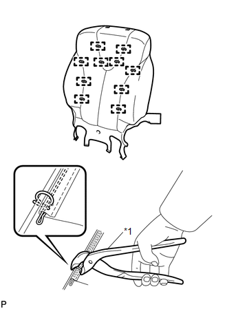
(b) Using hog ring pliers, install the separate type front seatback cover with 10 new hog rings. Text in Illustration
NOTICE:
|
|
2. INSTALL SEPARATE TYPE FRONT SEATBACK COVER WITH PAD
.gif)
3. INSTALL FRONT SEATBACK BOARD SUB-ASSEMBLY
4. INSTALL SEPARATE TYPE FRONT SEAT CUSHION COVER WITH PAD
5. INSTALL FRONT INNER SEAT CUSHION SHIELD
6. INSTALL FRONT SEAT INNER BELT ASSEMBLY
7. INSTALL POWER SEAT SWITCH
8. INSTALL FRONT SEAT CUSHION SHIELD ASSEMBLY
9. INSTALL SLIDE AND VERTICAL POWER SEAT SWITCH KNOB
10. INSTALL RECLINING POWER SEAT SWITCH KNOB
11. INSTALL FRONT SEAT ASSEMBLY
12. INSTALL FRONT SEAT REAR INNER TRACK COVER
13. INSTALL FRONT SEAT REAR OUTER TRACK COVER
14. INSTALL FRONT SEAT HEADREST ASSEMBLY
15. INSPECT FRONT SEAT ASSEMBLY
16. INSPECT SRS WARNING LIGHT
(See page )
 Inspection
INSPECTION
PROCEDURE
1. INSPECT FRONT SEATBACK HEATER LH
(a) Apply battery voltage and check the seatback heater.
OK:
Measurement Connection
Cond ...

Other materials about Toyota Venza:
Diagnosis System
DIAGNOSIS SYSTEM
1. DESCRIPTION
(a) Lighting system data and the Diagnostic Trouble Codes (DTCs) can be read
from the Data Link Connector 3 (DLC3) of the vehicle. When the system seems to be
malfunctioning, use the Techstream to check for malfunctions an ...
Front Passenger Seat Belt Warning Light
Components
COMPONENTS
ILLUSTRATION
Installation
INSTALLATION
PROCEDURE
1. INSTALL ACCESSORY METER ASSEMBLY (w/o Rear View Monitor System)
(a) Connect the connector.
(b) Engage the 2 clamps.
(c) Engage the 2 clips.
(d) Install the accessory mete ...
Problem Symptoms Table
PROBLEM SYMPTOMS TABLE
Use the table below to help determine the cause of problem symptoms.
If multiple suspected areas are listed, the potential causes of the symptoms
are listed in order of probability in the "Suspected Area" column ...

0.1215