Toyota Venza: Precaution
PRECAUTION
1. INITIALIZATION
NOTICE:
Perform the Registration (VIN registration) when replacing the ECM (See page
.gif) ).
).
HINT:
Reset memory or initialization cannot be completed by only disconnecting and reconnecting the cable of the negative (-) battery terminal.
2. FOR USING TECHSTREAM
CAUTION:
Observe the following items for safety reasons:
- Before using the Techstream, read the instruction manual.
- Prevent the Techstream cable from being caught on the pedals, shift lever or steering wheel when driving with the Techstream connected to the vehicle.
- When driving the vehicle for testing purposes using the Techstream, 2 persons are required. One is for driving the vehicle, and the other operates the Techstream.
3. DISCONNECTING AND RECONNECTING NEGATIVE (-) BATTERY CABLE
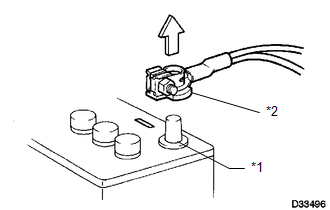
(a) Before performing work on electronic components, disconnect the cable from the negative (-) battery terminal to prevent damage to electrical system or electrical components.
Text in Illustration|
*1 |
Negative (-) Battery Terminal |
|
*2 |
Cable |
(b) Before disconnecting and reconnecting the battery cable, turn the ignition switch off and the headlight switch off. Then loosen the terminal nut completely. Do not damage the cable or terminal.
(c) When the battery cable is disconnected, the clock and radio settings and stored DTCs are cleared. Therefore, before disconnecting the battery cable, make a note of them.
NOTICE:
- When disconnecting and reconnecting the cable of the negative (-) battery terminal, the cowl top ventilator louver must also be removed and installed. Be sure to install the cowl top ventilator louver properly. If it is not installed properly, water may enter the engine compartment and cause malfunctions.
- When the cable is disconnected from the negative (-) battery terminal, initialize the following system(s) after the cable is reconnected.
|
System Name |
See Procedure |
|---|---|
|
Back Door Closer System |
|
|
Power Back Door System |
4. EXPRESSION OF IGNITION SWITCH
HINT:
The type of ignition switch used on this model differs according to the specifications of the vehicle.
The expressions listed in the table below are used in this section.
|
Expression |
Switch Type |
|
|---|---|---|
|
Ignition Switch (Position) |
Engine Switch (Condition) |
|
|
Ignition switch off |
LOCK |
Off (Lock) |
|
Ignition switch ON |
ON |
On (IG) |
|
Ignition switch ACC |
ACC |
On (ACC) |
|
Engine start |
START |
On (Start) |
 Sfi System
...
 Definition Of Terms
DEFINITION OF TERMS
Term
Definition
Monitor Description
Description of what the ECM monitors and how it detects malfunctions
(monitoring purpose ...
Other materials about Toyota Venza:
Starter Relay Circuit High (P0617)
DESCRIPTION
While the engine is being cranked, battery voltage is applied to terminal STA
of the TCM.
If the TCM detects the Starter Control (STA) signal while the vehicle is being
driven, it determines that there is a malfunction in the STA circuit. The ...
System Description
SYSTEM DESCRIPTION
1. GENERAL
This system has the following functions: manual slide open and close; auto slide
open; manual tilt up and down; auto tilt up; jam protection; key off operation.
2. FUNCTION OF MAIN COMPONENT
Component
O ...
Installation
INSTALLATION
PROCEDURE
1. TEMPORARILY TIGHTEN COMPRESSOR AND MAGNETIC CLUTCH
(a) Temporarily install the compressor and magnetic clutch and bracket
with the 4 bolts.
2. INSTALL COMPRESSOR AND MA ...

0.1365