Toyota Venza: Power Back Door cannot be Closed Using the Power Back Door Closer Switch
DESCRIPTION
When the power back door cannot be closed using the power back door closer switch, either of the following may be malfunctioning: 1) power back door closer switch circuit or 2) power back door ECU (power back door motor unit).
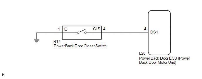
WIRING DIAGRAM
PROCEDURE
|
1. |
READ VALUE USING TECHSTREAM (POWER BACK DOOR CLOSER SWITCH) |
(a) Connect the Techstream to the DLC3.
(b) Turn the ignition switch to ON.
(c) Turn the Techstream on.
(d) Enter the following menus: Body Electrical / Back Door / Data List.
(e) Check the Data List to determine if the power back door closer switch functions properly.
Back Door (Power Back Door ECU)|
Tester Display |
Measurement Item/Range |
Normal Condition |
Diagnostic Note |
|---|---|---|---|
|
PBD Close SW |
Power back door closer switch signal / ON or OFF |
ON: Power back door closer switch on OFF: Power back door closer switch off |
- |
OK:
The power back door closer switch functions as specified in the normal condition column.
| OK | .gif) |
REPLACE POWER BACK DOOR ECU (POWER BACK DOOR MOTOR UNIT) |
|
.gif)
|
2. |
INSPECT POWER BACK DOOR CLOSER SWITCH |
|
(a) Remove the power back door closer switch (See page
|
|
.gif) ).
)..png)
(b) Measure the resistance according to the value(s) in the table below.
Standard Resistance:
|
Tester Connection |
Condition |
Specified Condition |
|---|---|---|
|
4 - 1 |
Pushed (on) |
Below 1 Ω |
|
4 - 1 |
Free (off) |
10 kΩ or higher |
|
*1 |
Component without harness connected (Power Back Door Closer Switch) |
| NG | |
REPLACE POWER BACK DOOR CLOSER SWITCH |
|
|
3. |
CHECK HARNESS AND CONNECTOR (POWER BACK DOOR CLOSER SWITCH - POWER BACK DOOR ECU) |
(a) Disconnect the R17 power back door closer switch and L20 power back door ECU connectors.
(b) Measure the resistance according to the value(s) in the table below.
Standard Resistance:
|
Tester Connection |
Condition |
Specified Condition |
|---|---|---|
|
R17-4 (CLS) - L20-4 (DS1) |
Always |
Below 1 Ω |
|
R17-1 (E) - Body ground |
Always |
Below 1 Ω |
|
R17-4 (CLS) - Body ground |
Always |
10 kΩ or higher |
| OK | |
REPLACE POWER BACK DOOR ECU (POWER BACK DOOR MOTOR UNIT) |
| NG | |
REPAIR OR REPLACE HARNESS OR CONNECTOR |
 Power Back Door cannot be Operated Using Any Switch
DESCRIPTION
When the power back door cannot be operated using any switch, one of the following
may be the cause: 1) initialization of the power back door ECU (power back door
motor unit), 2) powe ...
 Jam Protection Function Activates During Power Back Door Operation
DESCRIPTION
When the jam protection function activates during power back door operation,
one of the following may be the cause: 1) improper fit of back door, or a foreign
object is stuck in the b ...
Other materials about Toyota Venza:
How To Proceed With Troubleshooting
CAUTION / NOTICE / HINT
HINT:
Use the following procedure to troubleshoot the power mirror control
system.
*: Use the Techstream.
PROCEDURE
1.
VEHICLE BROUGHT TO WORKSHOP
NEXT
...
Abnormal Temperature Inside ID1 Tire (C2165/65-C2168/68)
DESCRIPTION
Each tire pressure warning valve and transmitter measures the tire internal temperature
as well as tire pressure, and transmits the information to the tire pressure warning
ECU along with the transmitter ID. If the measured temperature is out ...
Only Wireless Control Function is Inoperative
DESCRIPTION
The door control receiver receives signals from the transmitter and sends these
signals to the main body ECU. The main body ECU then controls all doors by sending
lock/unlock signals to each door, and sends hazard flasher relay signals to the ...

0.1621