Toyota Venza: Door Unlock Detection Switch Circuit
DESCRIPTION
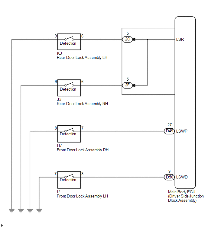
The main body ECU (driver side junction block assembly) detects the condition of the door unlock detection switch.
WIRING DIAGRAM
PROCEDURE
|
1. |
READ VALUE USING TECHSTREAM |
(a) Connect the Techstream to the DLC3.
(b) Turn the ignition switch to ON.
(c) Turn the Techstream on.
(d) Enter the following menus: Body Electrical / Main Body / Data List.
(e) Read the display on the Techstream.
Main Body|
Tester Display |
Measurement Item/Range |
Normal Condition |
Diagnostic Note |
|---|---|---|---|
|
D-Door Lock Pos SW |
Driver side door unlock detection switch signal/ON or OFF |
ON: Driver side door unlocked OFF: Driver side door locked |
- |
|
P-Door Lock Pos SW |
Front passenger side door unlock detection switch signal/ON or OFF |
ON: Front passenger side door unlocked OFF: Front passenger side locked |
- |
|
RL-Door Lock Pos SW |
Rear door unlock detection switch LH or RH signal/ON or OFF |
ON: Rear door LH or RH unlocked OFF: Rear door LH and RH locked |
- |
|
RR-Door Lock Pos SW |
Rear door unlock detection switch LH or RH signal/ON or OFF |
ON: Rear door LH or RH unlocked OFF: Rear door LH and RH locked |
- |
|
Result |
Proceed to |
|---|---|
|
OK |
A |
|
Driver side door unlock detection switch does not operate |
B |
|
Front passenger side door unlock detection switch does not operate |
C |
|
Rear door unlock detection switch LH does not operate |
D |
|
Rear door unlock detection switch RH does not operate |
E |
| A | .gif) |
PROCEED TO NEXT SUSPECTED AREA SHOWN IN PROBLEM SYMPTOMS TABLE |
| C | |
GO TO STEP 4 |
| D | |
GO TO STEP 6 |
| E | |
GO TO STEP 8 |
|
.gif)
|
2. |
INSPECT FRONT DOOR LOCK ASSEMBLY LH |
|
(a) Remove the front door lock assembly LH (See page
|
|
.gif) ).
).
(b) Measure the resistance according to the value(s) in the table below.
Standard Resistance:
|
Tester Connection |
Condition |
Specified Condition |
|---|---|---|
|
7 - 8 |
Locked |
10 kΩ or higher |
|
7 - 8 |
Unlocked |
Below 1 Ω |
|
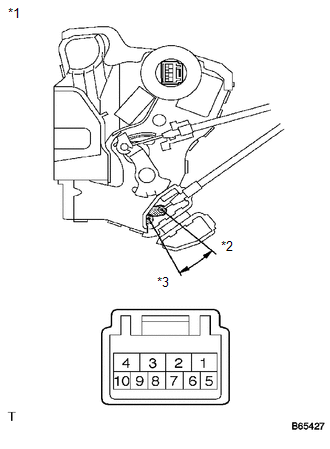
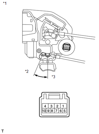
*1 |
Component without harness connected (Front Door Lock Assembly LH) |
|
*2 |
Unlock |
|
*3 |
Lock |
| NG | |
REPLACE FRONT DOOR LOCK ASSEMBLY LH |
|
|
3. |
CHECK HARNESS AND CONNECTOR (MAIN BODY ECU - FRONT DOOR LOCK ASSEMBLY LH) |
(a) Disconnect the I7 front door lock assembly LH connector.
(b) Disconnect D50 main body ECU (driver side junction block assembly) connector.
(c) Measure the resistance according to the value(s) in the table below.
Standard Resistance:
|
Tester Connection (Symbols) |
Condition |
Specified Condition |
|---|---|---|
|
I7-8 - D50-9 (LSWD) |
Always |
Below 1 Ω |
|
I7-8 - Body ground |
Always |
10 kΩ or higher |
|
I7-7 - Body ground |
Always |
Below 1 Ω |
|
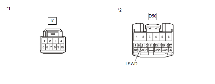
*1 |
Front view of wire harness connector (to Front Door Lock Assembly LH) |
|
*2 |
Front view of wire harness connector (to Main Body ECU (Driver Side Junction Block Assembly)) |
| OK | |
REPLACE MAIN BODY ECU (DRIVER SIDE JUNCTION BLOCK ASSEMBLY) |
| NG | |
REPAIR OR REPLACE HARNESS OR CONNECTOR |
|
4. |
INSPECT FRONT DOOR LOCK ASSEMBLY RH |
|
(a) Remove the front door lock assembly RH (See page
|
|
(b) Measure the resistance according to the value(s) in the table below.
Standard Resistance:
|
Tester Connection |
Condition |
Specified Condition |
|---|---|---|
|
7 - 8 |
Locked |
10 kΩ or higher |
|
7 - 8 |
Unlocked |
Below 1 Ω |
|
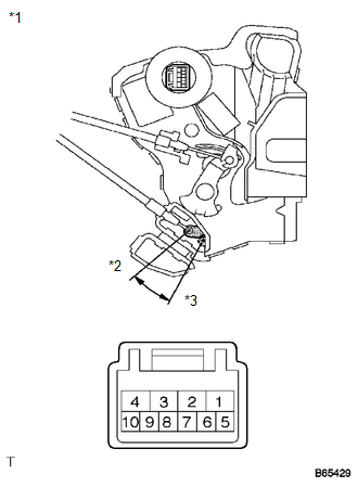
*1 |
Component without harness connected (Front Door Lock Assembly RH) |
|
*2 |
Unlock |
|
*3 |
Lock |
| NG | |
REPLACE FRONT DOOR LOCK ASSEMBLY RH |
|
|
5. |
CHECK HARNESS AND CONNECTOR (MAIN BODY ECU - FRONT DOOR LOCK ASSEMBLY RH) |
(a) Disconnect the H7 front door lock assembly RH connector.
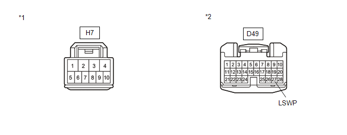
(b) Disconnect the D49 main body ECU (driver side junction block assembly) connector.
(c) Measure the resistance according to the value(s) in the table below.
Standard Resistance:
|
Tester Connection (Symbols) |
Condition |
Specified Condition |
|---|---|---|
|
H7-7 - D49-27 (LSWP) |
Always |
Below 1 Ω |
|
H7-7 - Body ground |
Always |
10 kΩ or higher |
|
H7-8 - Body ground |
Always |
Below 1 Ω |
|
*1 |
Front view of wire harness connector (to Front Door Lock Assembly RH) |
|
*2 |
Front view of wire harness connector (to Main Body ECU (Driver Side Junction Block Assembly)) |
| OK | |
REPLACE MAIN BODY ECU (DRIVER SIDE JUNCTION BLOCK ASSEMBLY) |
| NG | |
REPAIR OR REPLACE HARNESS OR CONNECTOR |
|
6. |
INSPECT REAR DOOR LOCK ASSEMBLY LH |
|
(a) Remove the rear door lock assembly LH (See page
|
|
(b) Measure the resistance according to the value(s) in the table below.
Standard Resistance:
|
Tester Connection |
Condition |
Specified Condition |
|---|---|---|
|
6 - 9 |
Locked |
10 kΩ or higher |
|
6 - 9 |
Unlocked |
Below 1 Ω |
|
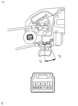
*1 |
Component without harness connected (Rear Door Lock Assembly LH) |
|
*2 |
Lock |
|
*3 |
Unlock |
| NG | |
REPLACE REAR DOOR LOCK ASSEMBLY LH |
|
|
7. |
CHECK HARNESS AND CONNECTOR (MAIN BODY ECU - REAR DOOR LOCK ASSEMBLY LH) |
|
(a) Disconnect the K3 rear door lock assembly LH connector. |
|
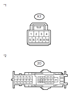
(b) Disconnect the 2O main body ECU (driver side junction block assembly) connector.
(c) Measure the resistance according to the value(s) in the table below.
Standard Resistance:
|
Tester Connection (Symbols) |
Condition |
Specified Condition |
|---|---|---|
|
K3-6 - 2O-5 |
Always |
Below 1 Ω |
|
K3-6 - Body ground |
Always |
10 kΩ or higher |
|
K3-9 - Body ground |
Always |
Below 1 Ω |
|
*1 |
Front view of wire harness connector (to Rear Door Lock Assembly LH) |
|
*2 |
Front view of wire harness connector (to Main Body ECU (Driver Side Junction Block Assembly)) |
| OK | |
REPLACE MAIN BODY ECU (DRIVER SIDE JUNCTION BLOCK ASSEMBLY) |
| NG | |
REPAIR OR REPLACE HARNESS OR CONNECTOR |
|
8. |
INSPECT REAR DOOR LOCK ASSEMBLY RH |
|
(a) Remove the rear door lock assembly RH (See page
|
|
(b) Measure the resistance according to the value(s) in the table below.
Standard Resistance:
|
Tester Connection |
Condition |
Specified Condition |
|---|---|---|
|
6 - 9 |
Locked |
10 kΩ or higher |
|
6 - 9 |
Unlocked |
Below 1 Ω |
|
*1 |
Component without harness connected (Rear Door Lock Assembly RH) |
|
*2 |
Lock |
|
*3 |
Unlock |
| NG | |
REPLACE REAR DOOR LOCK ASSEMBLY RH |
|
|
9. |
CHECK HARNESS AND CONNECTOR (MAIN BODY ECU - REAR DOOR LOCK ASSEMBLY RH) |
|
(a) Disconnect the J3 rear door lock assembly RH connector. |
|
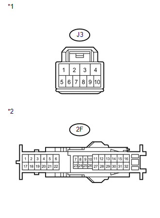
(b) Disconnect the 2F main body ECU (driver side junction block assembly) connector.
(c) Measure the resistance according to the value(s) in the table below.
Standard Resistance:
|
Tester Connection (Symbols) |
Condition |
Specified Condition |
|---|---|---|
|
J3-6 - 2F-5 |
Always |
Below 1 Ω |
|
J3-6 - Body ground |
Always |
10 kΩ or higher |
|
J3-9 - Body ground |
Always |
Below 1 Ω |
|
*1 |
Front view of wire harness connector (to Rear Door Lock Assembly RH) |
|
*2 |
Front view of wire harness connector (to Main Body ECU (Driver Side Junction Block Assembly)) |
| OK | |
REPLACE MAIN BODY ECU (DRIVER SIDE JUNCTION BLOCK ASSEMBLY) |
| NG | |
REPAIR OR REPLACE HARNESS OR CONNECTOR |
 Interior Light Power Source Circuit
DESCRIPTION
The main body ECU (driver side junction block assembly) controls operation of
the DOME CUT relay in order to supply power to the interior lights.
WIRING DIAGRAM
CAUTION / NOTICE / H ...
 Luggage Compartment Room Light
Components
COMPONENTS
ILLUSTRATION
Removal
REMOVAL
PROCEDURE
1. REMOVE NO. 2 ROOM LIGHT ASSEMBLY
(a) Using a moulding remover, disengage the claw.
...
Other materials about Toyota Venza:
Data List / Active Test
DATA LIST / ACTIVE TEST
1. DATA LIST
HINT:
Using the Techstream to read the Data List allows the values or states of switches,
sensors, actuators and other items to be read without removing any parts. This non-intrusive
inspection can be very useful bec ...
Front Door Speaker
Components
COMPONENTS
ILLUSTRATION
Removal
REMOVAL
PROCEDURE
1. DISCONNECT CABLE FROM NEGATIVE BATTERY TERMINAL
CAUTION:
Wait at least 90 seconds after disconnecting the cable from the negative (-)
battery terminal to disable the SRS system (Se ...
Communication Malfunction No. 1 (B2797)
DESCRIPTION
This DTC is stored when an error occurs in communication between the transponder
key amplifier and the transponder key ECU assembly.
HINT:
Some noise is found in the communication line.
DTC No.
DTC Detection Condition
...

0.1628