Toyota Venza: Heated Oxygen Sensor
Components
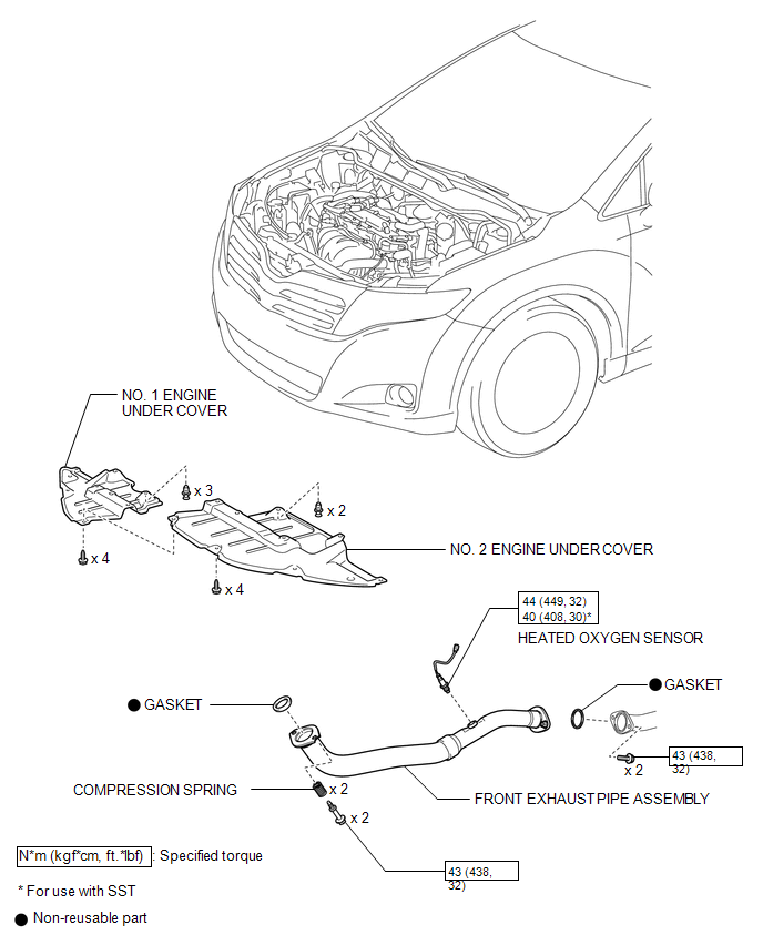
COMPONENTS
ILLUSTRATION
Removal
REMOVAL
PROCEDURE
1. REMOVE NO. 1 ENGINE UNDER COVER
2. REMOVE NO. 2 ENGINE UNDER COVER
3. REMOVE FRONT EXHAUST PIPE ASSEMBLY
.gif)
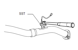
4. REMOVE HEATED OXYGEN SENSOR
|
(a) Using SST, remove the heated oxygen sensor from the front exhaust pipe assembly. SST: 09224-00011 |
|
Inspection
INSPECTION
PROCEDURE
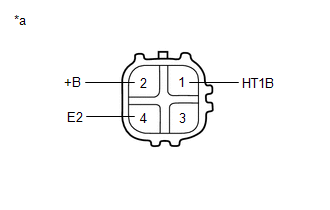
1. INSPECT HEATED OXYGEN SENSOR
|
(a) Measure the resistance according to the value(s) in the table below. Text in Illustration
Standard Resistance:
If the result is not as specified, replace the heated oxygen sensor. |
|
Installation
INSTALLATION
PROCEDURE
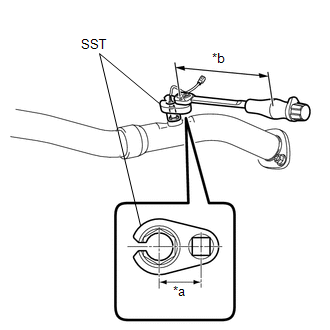
1. INSTALL HEATED OXYGEN SENSOR
HINT:
Perform "Inspection After Repair" after replacing the heated oxygen sensor (See
page .gif) ).
).
|
(a) Using SST, install the heated oxygen sensor to the front exhaust pipe assembly. Text in Illustration
SST: 09224-00011 Torque: without SST [Torque (N*m (kgf*cm, ft.*lbf))] : 44 N·m {449 kgf·cm, 32 ft·lbf} with SST [Reading of Torque wrench (N*m (kgf*cm, ft.*lbf))] : 40 N·m {408 kgf·cm, 30 ft·lbf} NOTICE: If the heated oxygen sensor has been struck or dropped, replace it. HINT:
|
|
2. INSTALL FRONT EXHAUST PIPE ASSEMBLY
3. INSPECT FOR EXHAUST GAS LEAK
4. INSTALL NO. 2 ENGINE UNDER COVER
5. INSTALL NO. 1 ENGINE UNDER COVER
6. PERFORM INITIALIZATION
(a) Perform "Inspection After Repair" after replacing the heated oxygen sensor
(See page ).
 Installation
INSTALLATION
PROCEDURE
1. INSTALL ENGINE COOLANT TEMPERATURE SENSOR
(a) Install a new gasket to the sensor.
Text in Illustration
*1
New Gasket
...
 Ignition Coil And Spark Plug
Components
COMPONENTS
ILLUSTRATION
Removal
REMOVAL
PROCEDURE
1. REMOVE NO. 1 ENGINE COVER SUB-ASSEMBLY
2. REMOVE IGNITION COIL ASSEMBLY
(a) Disconnect the 4 ignition coil assembly con ...
Other materials about Toyota Venza:
Does not Play even after Bluetooth Audio Mode is Selected
CAUTION / NOTICE / HINT
HINT:
Even if the portable player can play audio content, it may not be able to play
via the in-vehicle device. This does not necessarily indicate a malfunction of the
in-vehicle device.
PROCEDURE
1.
CHECK ...
Control Module Communication Bus OFF (U0073/94,U0100/65,U0123/62,U0124/95,U0126/63)
DESCRIPTION
The skid control ECU receives the signals from the ECM, steering angle sensor,
and yaw rate and acceleration sensor via the CAN communication system.
DTC Code
DTC Detection Condition
Trouble Area
...
Power Seat Power Easy Access System Function does not Operate
DESCRIPTION
When the ignition switch is off and shift lever is in P, the power seat slides
rearward when the seat belt tongue plate is disengaged from the front seat inner
belt assembly LH (auto away function). Also the power seat slides forward when the ...

0.1458