Toyota Venza: Atf Temperature Sensor(when Using The Engine Support Bridge)
Components
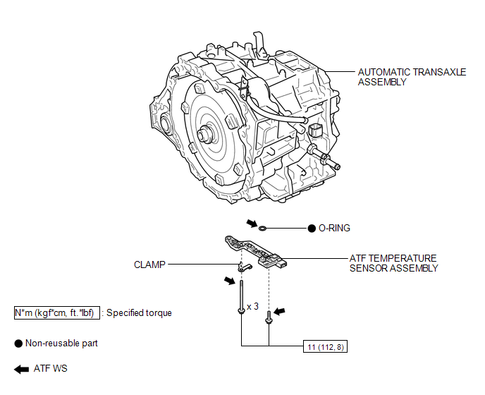
COMPONENTS
ILLUSTRATION
Inspection
INSPECTION
PROCEDURE
1. INSPECT ATF TEMPERATURE SENSOR ASSEMBLY
|
(a) Measure the resistance according to the value(s) in the table below. Standard Resistance:
If the resistance is out of the specified range with the ATF temperature shown in the preceding table, replace the ATF temperature sensor assembly. Otherwise, the driveability of the vehicle may decrease. |
|
.png)
Removal
REMOVAL
PROCEDURE
1. REMOVE VALVE BODY OIL STRAINER ASSEMBLY
See page .gif)
2. REMOVE ATF TEMPERATURE SENSOR ASSEMBLY
|
(a) Disconnect the ATF temperature sensor assembly connector. Text in Illustration
|
|
.png)
(b) Remove the 4 bolts, ATF temperature sensor assembly and clamp from the transmission valve body assembly.
|
(c) Remove the O-ring from the ATF temperature sensor assembly. Text in Illustration
|
|
.png)
Installation
INSTALLATION
PROCEDURE
1. INSTALL ATF TEMPERATURE SENSOR ASSEMBLY
(a) Coat a new O-ring with ATF and install it to the ATF temperature sensor assembly.
(b) Coat the 4 bolts with ATF.
|
(c) Install the ATF temperature sensor assembly and clamp to the transmission valve body assembly with the 4 bolts. Text in Illustration
Torque: 11 N·m {112 kgf·cm, 8 ft·lbf} Bolt Length: Bolt (A) 25 mm (0.984 in.) Bolt (B) 85 mm (3.35 in.) |
|
.png)
(d) Connect the ATF temperature sensor assembly connector.
2. INSTALL VALVE BODY OIL STRAINER ASSEMBLY
See page .gif)
 Installation
INSTALLATION
PROCEDURE
1. INSTALL ATF TEMPERATURE SENSOR ASSEMBLY
(a) Coat a new O-ring with ATF and install it to the ATF temperature
sensor assembly.
Text in Illustration
...

Other materials about Toyota Venza:
Power Mirrors do not Return to Memorized Position
SYSTEM DESCRIPTION
If either the M1 or M2 seat memory switch is pressed, the outer mirror control
ECU assembly (driver door) detects the seat memory switch status and sends the switch
signal to the main body ECU (driver side junction block assembly) via C ...
Light Control Switch Circuit
DESCRIPTION
The main body ECU (driver side junction block assembly) receives the following
switch information:
Light control switch position off, tail, head or AUTO
Dimmer switch position high, low or high flash (pass)
Fog light switch posit ...
Intake Air Control Valve Actuator(for Tcv)
Components
COMPONENTS
ILLUSTRATION
Removal
REMOVAL
PROCEDURE
1. REMOVE INTAKE MANIFOLD
(a) Remove the intake manifold (See page ).
2. REMOVE INTAKE AIR CONTROL VALVE ACTUATOR (for TCV)
(a) Remove the 2 bolts, intake air control valve actuator a ...

0.1699