Toyota Venza: Components
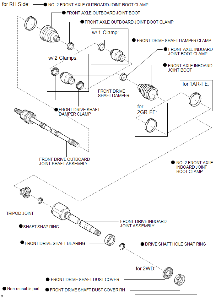
COMPONENTS
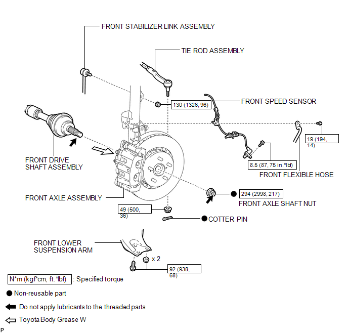
ILLUSTRATION
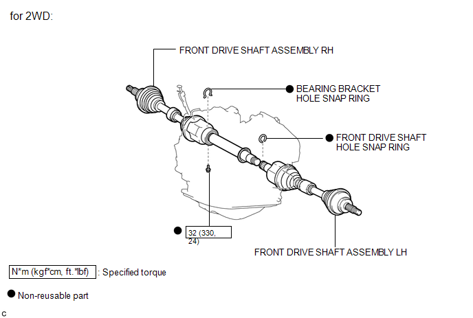
ILLUSTRATION
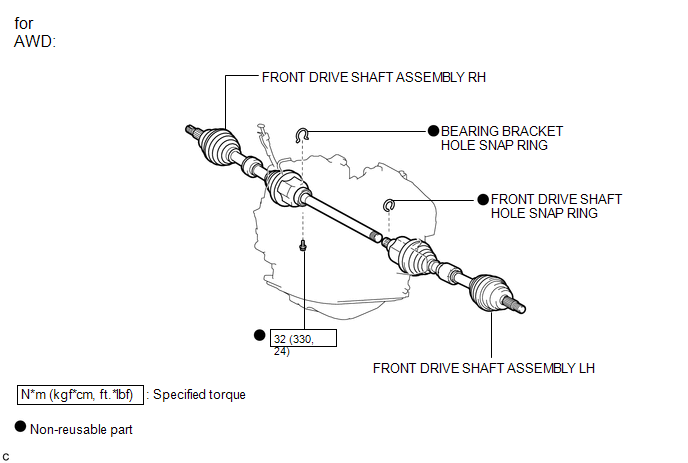
ILLUSTRATION
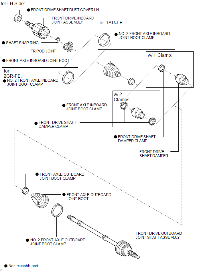
ILLUSTRATION
ILLUSTRATION

 Removal
REMOVAL
CAUTION / NOTICE / HINT
HINT:
Use the same procedure for the RH side and LH side.
The procedure listed below is for the LH side.
PROCEDURE
1. PRECAUTION
HINT:
See page ...
Other materials about Toyota Venza:
Installation
INSTALLATION
CAUTION / NOTICE / HINT
NOTICE:
When disconnecting the steering intermediate shaft assembly and pinion shaft
of steering gear assembly, be sure to place matchmarks before servicing.
PROCEDURE
1. INSTALL TIE ROD ASSEMBLY LH
(a) I ...
Engine Control System Malfunction (C1201/51)
DESCRIPTION
If a malfunction in the engine control system is detected, the operations of
VSC and TRAC are prohibited by the fail-safe function. When the signals from the
engine are input normally, the fail-safe is cancelled and the DTC is not stored.
...
Installation
INSTALLATION
PROCEDURE
1. INSTALL STUD BOLT (for LH Side)
(a) Install the stud bolt.
Torque:
17 N·m {173 kgf·cm, 13 ft·lbf}
2. INSTALL STUD BOLT (for RH Side)
HINT:
Perform the same proc ...

0.1526