Toyota Venza: Removal
REMOVAL
CAUTION / NOTICE / HINT
HINT:
- Use the same procedure for the RH side and LH side.
- The procedure listed below is for the LH side.
PROCEDURE
1. REMOVE REAR WHEEL
2. SEPARATE REAR DISC BRAKE CALIPER ASSEMBLY
.gif)
3. REMOVE REAR DISC
4. SEPARATE REAR SPEED SENSOR WIRE
5. SEPARATE NO. 3 PARKING BRAKE CABLE ASSEMBLY
6. REMOVE REAR AXLE HUB AND BEARING ASSEMBLY
7. REMOVE REAR STRUT ROD ASSEMBLY
8. REMOVE REAR AXLE CARRIER SUB-ASSEMBLY
|
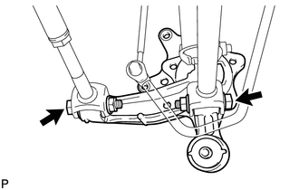
(a) Loosen the 2 bolts. NOTICE: Since stopper nuts are used, loosen the bolts. |
|
|
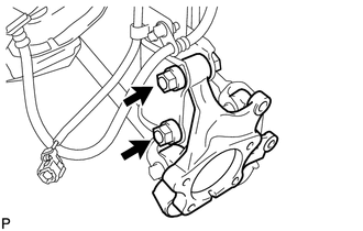
(b) Remove the 2 bolts and 2 nuts, and separate the rear axle carrier sub-assembly from the rear shock absorber with coil spring. NOTICE: When removing the nuts, keep the bolts from rotating. |
|
|
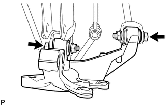
(c) Remove the 2 bolts, 2 nuts and rear axle carrier sub-assembly. |
|
 Components
COMPONENTS
ILLUSTRATION
...
 Installation
INSTALLATION
CAUTION / NOTICE / HINT
HINT:
Use the same procedure for the RH side and LH side.
The procedure listed below is for the LH side.
PROCEDURE
1. INSTALL REAR AXLE CARR ...
Other materials about Toyota Venza:
Wireless Door Lock Tuner Circuit Malfunction (B1242)
DESCRIPTION
The door control receiver is used to receive electrical waves relating to the
entry functions of the smart key system. The certification ECU (smart key ECU assembly)
decodes the requested smart key system operation by identifying a key code ba ...
Fail-safe Chart
FAIL-SAFE CHART
1. FAIL SAFE FUNCTION
(a) The following chart shows the status of the controls when the system is normal
and malfunctioning.
The passenger airbag ON/OFF indicator ("ON" and "OFF") comes on for
approximately 4 ...
Operation Check
OPERATION CHECK
1. INSPECT ILLUMINATED ENTRY SYSTEM OPERATION
NOTICE:
Perform this inspection with the customize parameters at the initial setting.
HINT:
The interior light control illuminates the lights below.
Transponder Key Amplifier*1
Roof ...

0.1129