Toyota Venza: Installation
INSTALLATION
CAUTION / NOTICE / HINT
HINT:
- Use the same procedure for the LH side and RH side.
- The following procedure is for the LH side.
- If the sensor rotor needs to be replaced, replace it together with the front drive shaft assembly.
PROCEDURE
1. INSTALL FRONT SPEED SENSOR
|
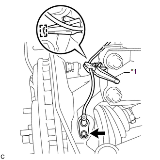
(a) Install the resin clamp and front speed sensor with the bolt. Torque: 8.5 N·m {87 kgf·cm, 75 in·lbf} NOTICE:
|
|
|
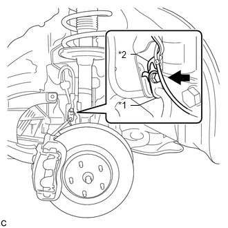
(b) Temporarily install the No. 1 sensor clamp. NOTICE: Be sure to insert the No. 1 sensor clamp claw into the stopper hole while installing the No. 1 sensor clamp. Text in Illustration
|
|
|
(c) Install the front brake flexible hose and No. 1 sensor clamp together to the shock absorber with the bolt. Torque: 19 N·m {194 kgf·cm, 14 ft·lbf} NOTICE:
|
|
|
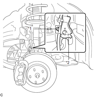
(d) Install the No. 2 sensor clamp to the body with the bolt. Torque: 8.0 N·m {82 kgf·cm, 71 in·lbf} Text in Illustration
|
|
.png)
|
(e) Install the 2 clamps and connect the front speed sensor connector. |
|
.png)
2. INSTALL FRONT FENDER LINER LH
.gif)
3. INSTALL FRONT FENDER OUTSIDE MOULDING LH
4. INSTALL FRONT WHEEL
Torque:
103 N·m {1050 kgf·cm, 76 ft·lbf}
5. CONNECT CABLE TO NEGATIVE BATTERY TERMINAL
NOTICE:
When disconnecting the cable, some systems need to be initialized after the cable
is reconnected (See page ).
6. CHECK FOR SPEED SENSOR SIGNAL
HINT:
(See page )
 Removal
REMOVAL
CAUTION / NOTICE / HINT
HINT:
Use the same procedure for the LH side and RH side.
The following procedure is for the LH side.
If the sensor rotor needs to be replaced, repla ...

Other materials about Toyota Venza:
Tire Pressure Warning Light Circuit
DESCRIPTION
If the tire pressure warning ECU detects a malfunction, the tire pressure warning
light blinks for 1 minute then stays on and tire pressure monitor is canceled at
the same time. At this time, the ECU records a DTC in the memory.
Connecting te ...
Back Door Closer does not Operate
DESCRIPTION
When the back door closer does not operate, one of the following may be the cause:
1) improper fit of the back door, or a foreign object is stuck in the back door
or 2) initialization of the power back door ECU (power back door motor unit)*1, ...
Components
COMPONENTS
ILLUSTRATION
ILLUSTRATION
ILLUSTRATION
ILLUSTRATION
ILLUSTRATION
...

0.1209