Toyota Venza: Installation
INSTALLATION
CAUTION / NOTICE / HINT
HINT:
- Use the same procedure for the RH side and LH side.
- The procedure listed below is for the LH side.
PROCEDURE
1. SECURE REAR SHOCK ABSORBER WITH COIL SPRING
.gif)
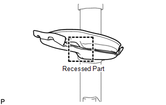
2. INSTALL REAR LOWER COIL SPRING INSULATOR
|
(a) Install the rear lower coil spring insulator onto the rear shock absorber assembly. NOTICE: Fit the recessed part of the rear lower coil spring insulator into the recession on the shock absorber assembly. |
|
3. INSTALL REAR NO. 1 SPRING BUMPER
|
(a) Install the rear No. 1 spring bumper to the rear shock absorber assembly. |
|
.png)
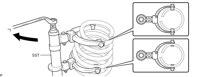
4. TEMPORARILY INSTALL REAR COIL SPRING
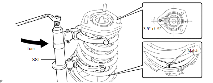
(a) Using SST, compress the rear coil spring.
 Text in Illustration
|
*1 |
Turn |
SST: 09727-30021
09727-00010
09727-00021
09727-00031
NOTICE:
Do not use an impact wrench. It will damage SST.
|
(b) Temporarily install the rear coil spring together with SST to the rear shock absorber assembly. |
|
.png)
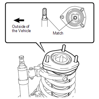
5. INSTALL REAR SUSPENSION SUPPORT ASSEMBLY
|
(a) Install the rear suspension support assembly to the rear shock absorber assembly. HINT: Align the cutout on the rear shock absorber assembly with the protrusion on the rear suspension support assembly by referring to the illustration. |
|
6. INSTALL REAR SUPPORT TO REAR SHOCK ABSORBER COLLAR
|
(a) Install the rear support to rear shock absorber collar to the rear shock absorber assembly. |
|
.png)
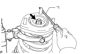
7. TEMPORARILY INSTALL REAR SUPPORT TO REAR SHOCK ABSORBER NUT
|
(a) Using a screwdriver or an equivalent tool to hold the rear suspension support assembly, temporarily install a new rear support to rear shock absorber nut to the rear shock absorber assembly. Text in Illustration
NOTICE:
HINT: Tape the screwdriver or the equivalent tool before use. |
|
8. INSTALL REAR COIL SPRING
(a) Install the rear coil spring.
NOTICE:
- Do not use an impact wrench. It will damage SST.
- Make sure that the end of the rear coil spring is positioned in the depression of the rear lower coil spring insulator.
- Ensure the rear lower coil spring insulator is not pinched or folded over and caught by the rear coil spring.
- Ensure that the stud bolt is positioned 3.5° to the outside of the vehicle as shown in the illustration. The deviation should be within +/- 5°.
9. INSTALL REAR SHOCK ABSORBER WITH COIL SPRING (for 2WD)
|
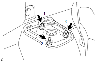
(a) Install the rear shock absorber with coil spring with the 3 nuts in order 1 to 3. Torque: 58 N·m {591 kgf·cm, 43 ft·lbf} |
|
|
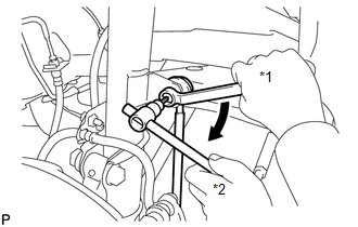
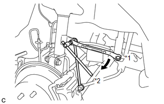
(b) Install the rear shock absorber with coil spring with the 2 bolts and 2 nuts. Torque: 290 N·m {2957 kgf·cm, 214 ft·lbf} NOTICE: When installing the nuts, keep the bolts from rotating. |
|
.png)
|
(c) Fully tighten the rear support to rear shock absorber nut. Torque: 55 N·m {561 kgf·cm, 41 ft·lbf} |
|
.png)
10. INSTALL REAR SHOCK ABSORBER WITH COIL SPRING (for AWD)
|
(a) Install the rear shock absorber with coil spring with the 3 nuts in order 1 to 3. Torque: 58 N·m {591 kgf·cm, 43 ft·lbf} |
|
|
(b) Install the rear shock absorber with coil spring with the 2 bolts and 2 nuts. Torque: 290 N·m {2957 kgf·cm, 214 ft·lbf} NOTICE: When installing the nuts, keep the bolts from rotating. |
|
.png)
|
(c) Fully tighten the rear support to rear shock absorber nut. Torque: 55 N·m {561 kgf·cm, 41 ft·lbf} |
|
11. INSTALL REAR NO. 1 SUSPENSION SUPPORT COVER
|
(a) Install the rear No. 1 suspension support cover. |
|
.png)
12. INSTALL REAR STABILIZER LINK ASSEMBLY (for 2WD)
|
(a) Install the rear stabilizer link assembly to the rear shock absorber with coil spring with the nut. Text in Illustration
Torque: 39 N·m {400 kgf·cm, 29 ft·lbf} HINT: If the ball joint turns together with the nut, use a hexagon wrench (5 mm) to hold the stud bolt. |
|
13. INSTALL REAR STABILIZER LINK ASSEMBLY (for AWD)
|
(a) Install the rear stabilizer link assembly to the rear shock absorber with coil spring with the nut. Text in Illustration
Torque: 39 N·m {400 kgf·cm, 29 ft·lbf} HINT: If the ball joint turns together with the nut, use a hexagon wrench (5 mm) to hold the stud bolt. |
|
14. INSTALL REAR SPEED SENSOR WIRE (for 2WD)
|
(a) Install the rear speed sensor wire to the rear shock absorber with coil spring with the bolt. Torque: 8.0 N·m {82 kgf·cm, 71 in·lbf} NOTICE: Do not twist the rear speed sensor wire when installing it. |
|
.png)
15. INSTALL REAR SPEED SENSOR (for AWD)
|
(a) Install the rear speed sensor to the rear shock absorber with coil spring with the bolt. Torque: 8.0 N·m {82 kgf·cm, 71 in·lbf} NOTICE: Do not twist the rear speed sensor wire when installing it. |
|
.png)
16. INSTALL REAR FLEXIBLE HOSE (for 2WD)
|
(a) Install the rear flexible hose to the rear shock absorber with coil spring with the bolt. Torque: 19 N·m {192 kgf·cm, 14 ft·lbf} NOTICE: Do not twist the rear flexible hose when installing it. |
|
.png)
17. INSTALL REAR FLEXIBLE HOSE (for AWD)
|
(a) Install the rear flexible hose to the rear shock absorber with coil spring with the bolt. Torque: 19 N·m {192 kgf·cm, 14 ft·lbf} NOTICE: Do not twist the rear flexible hose when installing it. |
|
.png)
18. INSTALL DECK SIDE TRIM
|
(a) Engage the 5 claws to install the deck side trim. |
|
.png)
19. INSTALL REAR WHEEL
Torque:
103 N·m {1050 kgf·cm, 76 ft·lbf}
20. INSPECT AND ADJUST REAR WHEEL ALIGNMENT
(a) Inspect and adjust the rear wheel alignment (See page
).
 Removal
REMOVAL
CAUTION / NOTICE / HINT
HINT:
Use the same procedure for the RH side and LH side.
The procedure listed below is for the LH side.
PROCEDURE
1. REMOVE REAR WHEEL
2. REMOV ...
 Disposal
DISPOSAL
PROCEDURE
1. DISPOSE OF REAR SHOCK ABSORBER
(a) Fully extend the shock absorber piston rod.
(b) Using a drill, make a hole in are ...
Other materials about Toyota Venza:
On-vehicle Inspection
ON-VEHICLE INSPECTION
CAUTION / NOTICE / HINT
CAUTION:
Be sure to follow the correct removal and installation procedures of the rear
airbag sensor.
PROCEDURE
1. INSPECT REAR AIRBAG SENSOR (VEHICLE NOT INVOLVED IN COLLISION)
(a) Perform a diagnostic sys ...
Terminals Of Ecm
TERMINALS OF ECM
HINT:
The standard voltage between each pair of ECM terminals is shown in the table
below. The appropriate conditions for checking each pair of terminals are also indicated.
The result of checks should be compared with the standard vol ...
Trip information
Display items can be switched by pressing the “INFO-CLOCK” button.
- Average fuel consumption (AVERAGE ECON)
Displays the average fuel consumption since the function was reset.
• The
function can be reset by pressing and holding the “RESET ...

0.1178