Toyota Venza: Terminals Of Ecu
TERMINALS OF ECU
1. TERMINALS OF ECU
 Text in Illustration
|
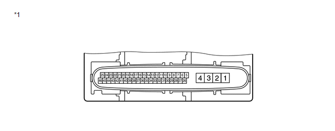
*1 |
Component without harness connected (Brake Actuator (Skid Control ECU)) |
|
Terminal No. (Symbol) |
Terminal Description |
|---|---|
|
1 (GND2) |
Pump motor ground |
|
2 (+BM) |
Motor relay power supply |
|
3 (+BS) |
Solenoid relay power supply |
|
4 (GND1) |
Skid control ECU ground |
|
5 (FL-) |
Front wheel speed LH (-) signal input |
|
6 (RL+) |
Rear wheel speed LH (+) signal input |
|
8 (RR+) |
Rear wheel speed RH (+) signal input |
|
9 (FR+) |
Front wheel speed RH (+) signal input |
|
10 (FR-) |
Front wheel speed RH (-) signal input |
|
11 (D/G) |
Diagnosis tester communication line |
|
13 (STP2) |
Stop light control relay input |
|
14 (CANL) |
CAN communication line L |
|
16 (TS) |
Sensor check input |
|
17 (CSW) |
VSC OFF switch input |
|
20 (FSW+) |
Brake pedal load sensing switch input |
|
26 (FL+) |
Front wheel speed LH (+) signal input |
|
27 (RL-) |
Rear wheel speed LH (-) signal input |
|
28 (IG1) |
ECU power supply |
|
29 (RR-) |
Rear wheel speed RH (-) signal input |
|
30 (STP) |
Stop light switch input |
|
33 (SP1) |
Speed signal output for speedometer |
|
35 (CANH) |
CAN communication line H |
|
39 (STP0) |
Stop light control relay output |
2. TERMINAL INSPECTION
(a) Disconnect the connector and measure the voltage and resistance on the wire harness side.
 Text in Illustration
|
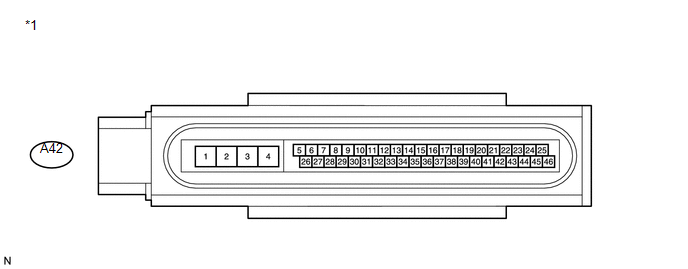
*1 |
Front view of wire harness connector (to Brake Actuator (Skid Control ECU)) |
HINT:
Voltage cannot be measured with the connector connected to the skid control ECU because the connector is watertight.
Standard|
Terminal No. (Symbol) |
Wiring Color |
Terminal Description |
Condition |
Specified Condition |
|---|---|---|---|---|
|
A42-1 (GND2) - Body ground |
W-B - Body ground |
Pump motor ground |
Always |
Below 1 Ω |
|
A42-2 (+BM) - Body ground |
Y - Body ground |
Motor relay power supply |
Always |
11 to 14 V |
|
A42-3 (+BS) - Body ground |
GR - Body ground |
Solenoid relay power supply |
Always |
11 to 14 V |
|
A42-4 (GND1) - Body ground |
W - Body ground |
Skid control ECU ground |
Always |
Below 1 Ω |
|
A42-13 (STP2) - Body ground |
R - Body ground |
Stop light control relay input |
Stop light switch ON → OFF (Brake pedal depressed → released) |
8 to 14 V → Below 1.5 V |
|
A42-17 (CSW) - Body ground |
LG - Body ground |
VSC OFF switch input |
VSC OFF switch held ON → OFF (Not pressed) |
Below 1 Ω → 10 kΩ or higher |
|
A42-20 (FSW+) - Body ground |
R - Body ground |
Brake pedal load sensing switch input |
Brake pedal load sensing switch OFF → ON (Brake pedal depressed → released) |
950 to 1050 Ω → 203 to 223 Ω |
|
A42-28 (IG1) - Body ground |
GR - Body ground |
ECU power supply |
Ignition switch ON |
11 to 14 V |
|
A42-30 (STP) - Body ground |
P - Body ground |
Stop light switch input |
Stop light switch ON → OFF (Brake pedal depressed → released) |
8 to 14 V → Below 1.5 V |
|
A42-39 (STP0) - Body ground |
BR - Body ground |
Stop light control relay output |
Ignition switch ON |
11 to 14 V |
 Problem Symptoms Table
PROBLEM SYMPTOMS TABLE
If there are no DTCs output and the problem still occurs, check the circuits
for each problem symptom in the order given in the following table and proceed to
the relevant ...
 Diagnosis System
DIAGNOSIS SYSTEM
1. DESCRIPTION
When troubleshooting a vehicle with a diagnosis system, the only difference from
the usual troubleshooting procedure is connecting the Techstream to the vehicle
a ...
Other materials about Toyota Venza:
ECM Communication Stop Mode
DESCRIPTION
Detection Item
Symptom
Trouble Area
ECM Communication Stop Mode
"Engine" and "ECT" are not displayed on "CAN Bus Check" screen
of the Techs ...
Transmission Range Sensor Circuit Malfunction (PRNDL Input) (P0705)
DESCRIPTION
The park/neutral position switch assembly detects the shift lever position and
sends signals to the ECM.
DTC No.
DTC Detection Condition
Trouble Area
P0705
One of the following condit ...
How To Proceed With Troubleshooting
CAUTION / NOTICE / HINT
HINT:
*: Use the Techstream
PROCEDURE
1.
VEHICLE BROUGHT TO WORKSHOP
NEXT
2.
CUSTOMER PROBLEM ANALYSIS
...

0.1564