Toyota Venza: Removal
REMOVAL
PROCEDURE
1. REMOVE REAR DOOR SCUFF PLATE RH
HINT:
Use the same procedure for the RH side and the LH side (See page
.gif) ).
).
2. REMOVE REAR DOOR OPENING TRIM WEATHERSTRIP RH
HINT:
Use the same procedure for the RH side and the LH side (See page
).
3. REMOVE TONNEAU COVER ASSEMBLY (w/ Tonneau Cover)
4. REMOVE DECK BOARD ASSEMBLY
5. REMOVE NO. 3 DECK BOARD SUB-ASSEMBLY
6. REMOVE DECK SIDE TRIM BOX LH
7. REMOVE NO. 2 DECK BOARD SUB-ASSEMBLY
8. REMOVE DECK SIDE TRIM BOX RH
9. REMOVE NO. 1 DECK BOARD
10. REMOVE REAR SEAT SUB FLOOR PANEL ASSEMBLY
11. REMOVE REAR FLOOR FINISH PLATE
12. REMOVE REAR SEAT HEADREST ASSEMBLY
13. REMOVE REAR SEAT CENTER HEADREST ASSEMBLY
14. REMOVE REAR SEAT INNER TRACK BRACKET COVER
15. REMOVE REAR SEAT OUTER TRACK BRACKET COVER
16. DISCONNECT REAR SEAT RECLINING CONTROL CABLE
17. REMOVE REAR SEAT ASSEMBLY RH
18. REMOVE RECLINING REMOTE CONTROL BEZEL RH
HINT:
Use the same procedure for the RH side and the LH side (See page
).
19. REMOVE LUGGAGE HOLD BELT STRIKER ASSEMBLY
HINT:
Use the same procedure for the RH side and the LH side (See page
).
20. DISCONNECT REAR SEAT OUTER BELT ASSEMBLY RH
HINT:
Use the same procedure for the RH side and the LH side (See page
).
21. REMOVE DECK TRIM SIDE PANEL ASSEMBLY RH
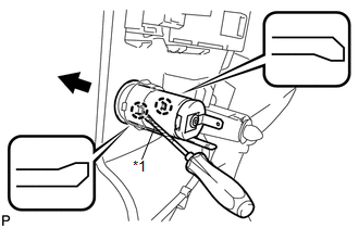
22. REMOVE REAR POWER POINT SOCKET ASSEMBLY
|
(a) Using a screwdriver, disengage the 2 claws and remove the rear power point socket assembly as shown in the illustration. Text in Illustration
HINT: Tape the screwdriver tip before use. |
|
23. REMOVE REAR POWER POINT SOCKET COVER
|
(a) Disengage the 2 claws and remove the rear power point socket cover. |
|
.png)
 Installation
INSTALLATION
PROCEDURE
1. INSTALL REAR POWER POINT SOCKET COVER
(a) Engage the 2 claws to install the rear power point socket cover.
2. IN ...
 Seat
Seat
...
Other materials about Toyota Venza:
System Description
SYSTEM DESCRIPTION
1. FRONT POWER SEAT CONTROL SYSTEM DESCRIPTION
The driver seat is equipped with slide, reclining, lifter, front vertical and
lumbar support adjustment functions.
2. FUNCTION OF MAIN COMPONENTS
The following functions are available:
...
Charge Warning Light Comes ON while Driving
PROCEDURE
1.
CHECK LOCK FUNCTION OF GENERATOR CLUTCH PULLEY
(a) Check the lock function with the pulley installed in the vehicle.
(1) Visually check that the rotor in the generator operates with the engine running.
(b) Check ...
Fuel pump shut off system
To minimize the risk of fuel leakage when the engine stalls or an airbag inflates
upon collision, the fuel pump shut off system stops supplying fuel to the engine.
Follow the procedure below to restart the engine after the system is activated.
►Vehic ...

0.1466