Toyota Venza: Check Mode Procedure
CHECK MODE PROCEDURE
1. DESCRIPTION
(a) Check mode has a higher sensitivity to malfunctions and can detect malfunctions that normal mode cannot detect. Check mode can also detect all the malfunctions that normal mode can detect. In check mode, DTCs are detected with 1 trip detection logic.
2. CHECK MODE PROCEDURE
(a) Make sure that the following conditions are met:
(1) Battery positive voltage 11 V or more.
(2) Throttle valve fully closed.
(3) Shift lever in P or N.
(4) A/C off.
(b) Turn the ignition switch off.
(c) Connect the Techstream to the DLC3.
(d) Turn the ignition switch to ON.
(e) Turn the Techstream on.
(f) Enter the following menus: Powertrain / ECT / Check Mode.
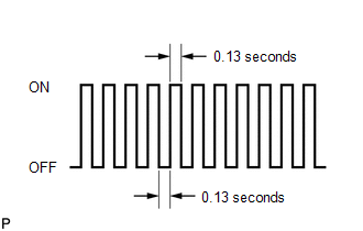
(g) Change the TCM to check mode. Make sure the MIL flashes as shown in the illustration.
NOTICE:
All DTCs and freeze frame data will be cleared if: 1) the Techstream is used to change the TCM from normal mode to check mode or vice versa; or 2) during check mode, the ignition switch is turned from ON to ACC or off.
Before entering check mode, make notes of the DTCs and freeze frame data.
(h) Start the engine. The MIL should turn off after the engine starts.
(i) Perform Monitor Drive Pattern for the ECT test (See page
.gif) ).
).
(Or, simulate the conditions of the malfunction described by the customer.)
(j) After simulating the malfunction conditions, use the Techstream to check the DTC and freeze frame data.
 Dtc Check / Clear
DTC CHECK / CLEAR
NOTICE:
When the diagnosis system is changed from normal mode to check mode or vice versa,
all DTCs and freeze frame data recorded in normal mode are cleared. Before changing
m ...
 Fail-safe Chart
FAIL-SAFE CHART
1. Fail-safe
This function minimizes the loss of operation when any abnormality occurs in
a sensor or solenoid.
Fail-safe Control List
Malfunction Part
Func ...
Other materials about Toyota Venza:
Intake Air Temperature Circuit Low Input (P0112,P0113)
DESCRIPTION
The intake air temperature sensor, in the mass air flow meter, monitors
the intake air temperature. The intake air temperature sensor has a built-in
thermistor with a resistance that varies according to the temperature of
the ...
Diagnosis System
DIAGNOSIS SYSTEM
1. DESCRIPTION
(a) When troubleshooting On-Board Diagnostic (OBD II) vehicles, the vehicle must
be connected to the OBD II scan tool (complying with SAE J1987). Various data output
from the vehicle TCM can then be read.
(b) OBD II regul ...
Diagnosis System
DIAGNOSIS SYSTEM
1. DESCRIPTION
(a) The certification ECU (smart key ECU assembly) and ECM control the vehicle
engine immobiliser system functions. Engine immobiliser system data and Diagnostic
Trouble Codes (DTCs) can be read through the vehicle Data Li ...

0.1651