Toyota Venza: ACC Signal Circuit
DESCRIPTION
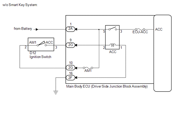
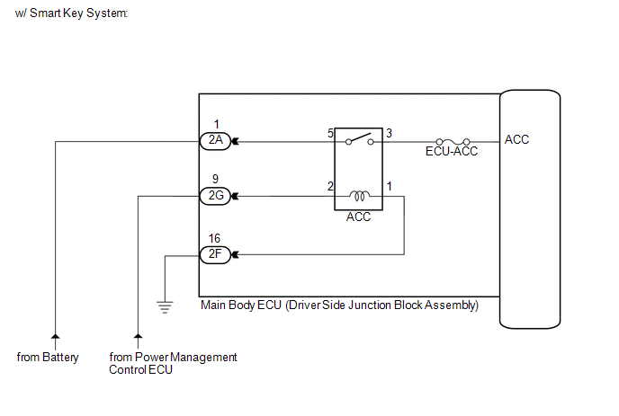
This circuit detects the ignition switch ACC or off condition, and sends it to the main body ECU (driver side junction block assembly).
WIRING DIAGRAM
CAUTION / NOTICE / HINT
NOTICE:
Inspect the fuses for circuits related to this system before performing the following inspection procedure.
PROCEDURE
|
1. |
READ VALUE USING TECHSTREAM |
(a) Connect the Techstream to the DLC3.
(b) Turn the ignition switch to ON.
(c) Turn the Techstream on.
(d) Enter the following menus: Body Electrical / Main Body / Data List.
(e) Read the display on the Techstream.
Main Body|
Tester Display |
Measurement Item/Range |
Normal Condition |
Diagnostic Note |
|---|---|---|---|
|
ACC SW |
Ignition switch or engine switch ACC signal/ON or OFF |
ON: Ignition switch ACC OFF: Ignition switch off |
- |
OK:
Normal conditions listed above are displayed.
| OK | .gif) |
PROCEED TO NEXT SUSPECTED AREA SHOWN IN PROBLEM SYMPTOMS TABLE |
|
.gif)
|
2. |
INSPECT ACC RELAY |
|
(a) Remove the ACC relay from the main body ECU (driver side junction block assembly). |
|
.png)
(b) Measure the resistance according to the value(s) in the table below.
Standard Resistance:
|
Tester Connection |
Condition |
Specified Condition |
|---|---|---|
|
3 - 5 |
When battery voltage is not applied to terminals 1 and 2 |
10 kΩ or higher |
|
When battery voltage is applied to terminals 1 and 2 |
Below 1 Ω |
| NG | |
REPLACE ACC RELAY |
|
|
3. |
CHECK HARNESS AND CONNECTOR (MAIN BODY ECU - BATTERY AND BODY GROUND) |
|
(a) Disconnect the 2A main body ECU (driver side junction block assembly) connector. |
|
.png)
(b) Measure the voltage according to the value(s) in the table below.
Standard Voltage:
|
Tester Connection |
Condition |
Specified Condition |
|---|---|---|
|
2A-1 - Body ground |
Always |
11 to 14 V |
|
*1 |
Front view of wire harness connector (to Main Body ECU (Driver Side Junction Block Assembly)) |
|
(c) Disconnect the 2F main body ECU (driver side junction block assembly) connector. |
|
.png)
(d) Measure the resistance according to the value(s) in the table below.
Standard Resistance:
|
Tester Connection |
Condition |
Specified Condition |
|---|---|---|
|
2F-16 - Body ground |
Always |
Below 1 Ω |
|
*1 |
Front view of wire harness connector (to Main Body ECU (Driver Side Junction Block Assembly)) |
| NG | |
REPAIR OR REPLACE HARNESS OR CONNECTOR |
|
|
4. |
CHECK VEHICLE CONDITION |
(a) Check the vehicle condition.
|
Condition |
Proceed to |
|---|---|
|
w/o Smart Key System |
A |
|
w/ Smart Key System |
B |
| B | |
GO TO STEP 7 |
|
|
5. |
CHECK HARNESS AND CONNECTOR (MAIN BODY ECU - IGNITION SWITCH) |
|
(a) Disconnect the D12 ignition switch connector. |
|
(b) Disconnect the 2G main body ECU (driver side junction block assembly) connector.
(c) Measure the resistance according to the value(s) in the table below.
Standard Resistance:
|
Tester Connection |
Condition |
Specified Condition |
|---|---|---|
|
2G-9 - D12-3 (ACC) |
Always |
Below 1 Ω |
|
2G-10 - D12-2 (AM1) |
Always |
Below 1 Ω |
|
2G-9 - Body ground |
Always |
10 kΩ or higher |
|
2G-10 - Body ground |
Always |
10 kΩ or higher |
|
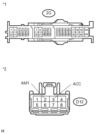
*1 |
Front view of wire harness connector (to Main Body ECU (Driver Side Junction Block Assembly)) |
|
*2 |
Front view of wire harness connector (to Ignition Switch) |
| NG | |
REPAIR OR REPLACE HARNESS OR CONNECTOR |
|
|
6. |
INSPECT IGNITION SWITCH |
|
(a) Measure the resistance according to the value(s) in the table below. Standard Resistance:
|
|
| OK | |
REPLACE MAIN BODY ECU (DRIVER SIDE JUNCTION BLOCK ASSEMBLY) |
| NG | |
REPLACE IGNITION SWITCH |
|
7. |
CHECK HARNESS AND CONNECTOR (POWER MANAGEMENT CONTROL ECU - MAIN BODY ECU) |
|
(a) Disconnect the 2G main body ECU (driver side junction block assembly) connector. |
|
.png)
(b) Measure the voltage according to the value(s) in the table below.
Standard Voltage:
|
Tester Connection |
Condition |
Specified Condition |
|---|---|---|
|
2G-9 - Body ground |
Engine switch on (ACC) |
11 to 14 V |
|
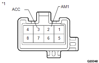
*1 |
Front view of wire harness connector (to Main Body ECU (Driver Side Junction Block Assembly)) |
| OK | |
REPLACE MAIN BODY ECU (DRIVER SIDE JUNCTION BLOCK ASSEMBLY) |
| NG | |
REPAIR OR REPLACE HARNESS OR CONNECTOR |
 IG Signal Circuit
DESCRIPTION
This circuit detects the ignition switch ON or off condition, and sends it to
the main body ECU (driver side junction block assembly).
WIRING DIAGRAM
CAUTION / NOTICE / HINT
NOTI ...
 Door Courtesy Switch Circuit
DESCRIPTION
The main body ECU (driver side junction block assembly) detects the condition
of the door courtesy light switch.
WIRING DIAGRAM
PROCEDURE
1.
READ VALUE USING ...
Other materials about Toyota Venza:
Engine does not Start
DESCRIPTION
1. ENGINE START SYSTEM FUNCTION
(a) If the engine switch is pressed with the shift lever in P or N and the brake
pedal depressed, the power management control ECU determines that this is an engine
start request.
(b) The certification ECU (sm ...
Operation Check
OPERATION CHECK
1. SMART KEY SYSTEM OPERATION INSPECTION
(a) Check the entry unlock function.
(1) Use the wireless lock operation to lock the doors. With the key outside the
vehicle, touch a front door outside handle assembly (touch sensor) and check that ...
Engine Hood Courtesy Switch Circuit
DESCRIPTION
The security courtesy switch is installed together with the hood lock. This switch
turns off when the engine hood is opened and turns on when the engine hood is closed.
WIRING DIAGRAM
PROCEDURE
1.
INSPECT HOOD LOCK AS ...

0.1451