Toyota Venza: Pressure Control Solenoid "A" Electrical (Shift Solenoid Valve SL1) (P0748)
DESCRIPTION
Changing from 1st to 6th is performed by the TCM turning shift solenoid valves
SL1, SL2, SL3, SL4 and SL on and off. If an open or short circuit occurs in any
of the shift solenoid valves, the TCM controls the remaining normal shift solenoid
valves to allow the vehicle to be operated (See page
.gif) ).
).
|
DTC No. |
DTC Detection Condition |
Trouble Area |
|---|---|---|
|
P0748 |
The TCM checks for an open or short in the shift solenoid valve SL1 circuit while driving and shifting between 4th and 5th gears. (1-trip detection logic)
|
|
MONITOR DESCRIPTION
This DTC indicates an open or short in the shift solenoid valve SL1 circuit. The TCM commands gear shifts by turning the shift solenoid valves on or off. When there is an open or short circuit in any shift solenoid valve circuit, the TCM detects the problem and illuminates the MIL and stores the DTC. The TCM also performs the fail-safe function and turns the other normal shift solenoid valves on or off. (In case of an open or short circuit, the TCM stops sending current to the circuit.)
While driving and shifting between 4th and 5th gears, if the TCM detects an open
or short in the shift solenoid valve SL1 circuit, the TCM determines there is a
malfunction (See page ).
MONITOR STRATEGY
|
Related DTCs |
P0748: Shift solenoid valve SL1/Range check |
|
Required sensors/Components |
Shift solenoid valve SL1 |
|
Frequency of operation |
Continuous |
|
Duration |
1 sec. |
|
MIL operation |
Immediate |
|
Sequence of operation |
None |
TYPICAL ENABLING CONDITIONS
All|
The monitor will run whenever the following DTCs are not present |
None |
|
Ignition switch |
ON |
|
Starter |
OFF |
|
Battery voltage |
12 V or more |
|
Battery voltage |
10 V or more and less than 12 V |
|
Target current |
Less than 0.75 A |
|
Battery voltage |
8 V or more |
|
Target current |
0.25 A or more |
TYPICAL MALFUNCTION THRESHOLDS
Condition (A) and (B)|
Output duty cycle |
100% or more |
|
Output duty cycle |
0% or less |
COMPONENT OPERATING RANGE
|
Output duty cycle |
More than 3% and less than 100% |
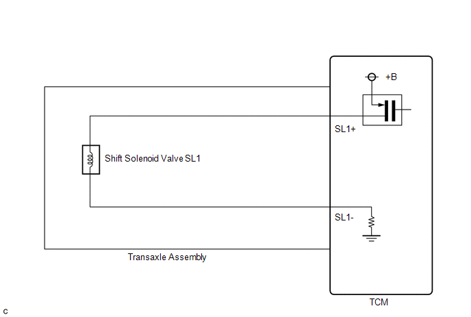
WIRING DIAGRAM
CAUTION / NOTICE / HINT
NOTICE:
Perform the universal trip to clear permanent DTCs (See page
).
HINT:
The following table shows normal operation of the shift solenoid valve SL1 when the shift lever is in D:
|
TCM commanded gear |
1st |
2nd |
3rd |
4th |
5th |
6th |
|
Shift solenoid valve SL1 |
ON |
ON |
ON |
ON |
OFF |
OFF |
PROCEDURE
|
1. |
INSPECT TRANSMISSION WIRE (SL1) |
|
(a) Remove the TCM from the transaxle. |
|
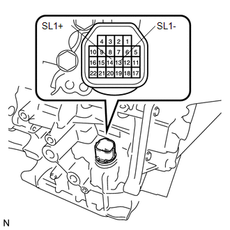
(b) Measure the resistance according to the value(s) in the table below.
Standard Resistance:
|
Tester Connection |
Condition |
Specified Condition |
|---|---|---|
|
14 (SL1+) - 13 (SL1-) |
20°C (68°F) |
5.0 to 5.6 Ω |
|
14 (SL1+) - Body ground |
Always |
10 kΩ or higher |
|
13 (SL1-) - Body ground |
Always |
10 kΩ or higher |
|
14 (SL1+) - All other terminals except 13 (SL1-) |
Always |
10 kΩ or higher |
|
13 (SL1-) - All other terminals except 14 (SL1+) |
Always |
10 kΩ or higher |
| OK | .gif) |
REPLACE TCM |
|
.gif)
|
2. |
INSPECT SHIFT SOLENOID VALVE SL1 |
(a) Remove shift solenoid valve SL1.
.png)
(b) Measure the resistance according to the value(s) in the table below.
Standard Resistance:
|
Tester Connection |
Condition |
Specified Condition |
|---|---|---|
|
1 - 2 |
20°C (68°F) |
5.0 to 5.6 Ω |
|
*1 |
Shift Solenoid Valve SL1 |
(c) Connect a battery positive (+) lead with a 21 W bulb to terminal 2 and a negative (-) lead to terminal 1 of the solenoid valve connector. Then check that the valve moves and makes an operating sound.
OK:
Valve moves and makes an operating sound.
| OK | |
REPLACE TRANSMISSION WIRE |
| NG | |
REPLACE SHIFT SOLENOID VALVE SL1 |
 Pressure Control Solenoid "B" Electrical (Shift Solenoid Valve SL2) (P0778)
DESCRIPTION
Changing from 1st to 6th is performed by the TCM turning shift solenoid valves
SL1, SL2, SL3, SL4 and SL on and off. If an open or short circuit occurs in any
of the shift solenoid va ...
 Pressure Control Solenoid "A" Performance (Shift Solenoid Valve SL1) (P0746)
SYSTEM DESCRIPTION
The TCM uses the vehicle speed signal and signals from the transmission speed
sensors (NC, NT) to detect the actual gear (1st, 2nd, 3rd, 4th, 5th or 6th gear).
Then the TCM comp ...
Other materials about Toyota Venza:
Lost Communication with AFS LIN (B124D)
DESCRIPTION
Refer to DTC B124D (Lighting system) (See page
).
DTC No.
DTC Detection Condition
Trouble Area
B124D
Malfunctions in LIN communication system
Inner rear view mir ...
Torque Converter Clutch Solenoid Performance (Shift Solenoid Valve SL) (P0741)
SYSTEM DESCRIPTION
The TCM uses signals from the throttle position sensor, air-flow meter, turbine
(input) speed sensor, intermediate (counter gear) speed sensor and crankshaft position
sensor to help determine the engagement timing of the lock-up clutch. ...
Removal
REMOVAL
CAUTION / NOTICE / HINT
HINT:
Perform "Inspection After Repair" after replacing the fuel pump assembly (See
page ).
PROCEDURE
1. DISCHARGE FUEL SYSTEM PRESSURE
(a) Discharge fuel system pressure (See page
).
2. DISCONNECT CABLE FR ...

0.1807