Toyota Venza: Removal
REMOVAL
CAUTION / NOTICE / HINT
HINT:
- Use the same procedure for the RH side and LH side.
- The procedure listed below is for the LH side.
PROCEDURE
1. REMOVE REAR WHEEL
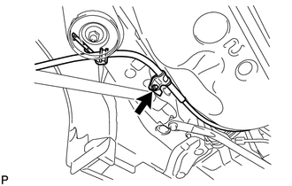
2. SEPARATE NO. 3 PARKING BRAKE CABLE ASSEMBLY
|
(a) Remove the bolt and separate the No. 3 parking brake cable assembly. |
|
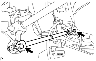
3. REMOVE REAR STRUT ROD ASSEMBLY (for 2WD)
|
(a) Remove the 2 bolts, the 2 nuts and the rear strut rod assembly. NOTICE: Since stopper nuts are used, loosen the bolts. |
|
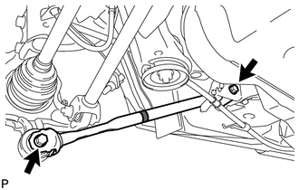
4. REMOVE REAR STRUT ROD ASSEMBLY (for AWD)
|
(a) Remove the 2 bolts, the 2 nuts and the rear strut rod assembly. NOTICE: Since stopper nuts are used, loosen the bolts. |
|
 Components
COMPONENTS
ILLUSTRATION
ILLUSTRATION
...
 Installation
INSTALLATION
CAUTION / NOTICE / HINT
HINT:
Use the same procedure for the RH side and LH side.
The procedure listed below is for the LH side.
PROCEDURE
1. INSTALL REAR STRUT ROD ...
Other materials about Toyota Venza:
Adjustment
ADJUSTMENT
PROCEDURE
1. INSPECT TIRES
(a) Inspect the tires (See page ).
2. MEASURE VEHICLE HEIGHT
NOTICE:
Before inspecting the wheel alignment, adjust the vehicle height to
the specified value.
Be sure to perform measurement on a level ...
Data List / Active Test
DATA LIST / ACTIVE TEST
1. DATA LIST
HINT:
Using the Techstream to read the Data List allows the values or states of switches,
sensors, actuator and other items to be read without removing any parts. This non-intrusive
inspection can be very useful beca ...
Rear Brake Flexible Hose
Components
COMPONENTS
ILLUSTRATION
Removal
REMOVAL
CAUTION / NOTICE / HINT
NOTICE:
If both the left and right side hoses are removed at the same time, be sure to
place identification marks indicating the position on each side.
HINT:
Us ...

0.1582