Toyota Venza: Installation
INSTALLATION
CAUTION / NOTICE / HINT
NOTICE:
- Do not replace the spiral cable with the battery connected and the ignition switch ON.
- Do not rotate the spiral cable without the steering wheel with the battery connected and the ignition switch ON.
- Ensure that the steering wheel is installed and aligned straight when inspecting the steering sensor.
PROCEDURE
1. INSTALL STEERING SHAKE DAMPER
(a) Install the steering shake damper to the steering wheel sub-assembly with the 2 screws.
Torque:
2.4 N·m {24 kgf·cm, 21 in·lbf}
2. INSTALL CRUISE CONTROL SWITCH WIRE
3. INSTALL CRUISE CONTROL MAIN SWITCH
.gif)
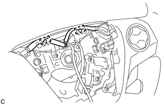
4. INSTALL STEERING PAD SWITCH ASSEMBLY
(a) Engage the 2 claws, 2 pins and 2 guides to install the steering pad switch assembly.
(b) Install the 2 screws.
Torque:
2.4 N·m {24 kgf·cm, 21 in·lbf}
|
(c) Pass the wire harness over the 2 guides. |
|
5. TURN FRONT WHEELS TO FACE STRAIGHT AHEAD
6. ADJUST SPIRAL CABLE WITH SENSOR SUB-ASSEMBLY
7. INSTALL STEERING WHEEL ASSEMBLY
|
(a) Install the steering wheel assembly aligning the matchmarks on the steering wheel assembly and steering main shaft. Text in Illustration
|
|
.png)
(b) Install the steering wheel assembly set nut.
Torque:
50 N·m {510 kgf·cm, 37 ft·lbf}
(c) Connect each connector to the spiral cable sub-assembly.
8. INSPECT STEERING WHEEL CENTER POINT
9. INSTALL STEERING PAD
(See page )
 Removal
REMOVAL
CAUTION / NOTICE / HINT
NOTICE:
Do not replace the spiral cable with the battery connected and the ignition
switch ON.
Do not rotate the spiral cable without the steering wh ...

Other materials about Toyota Venza:
Precaution
PRECAUTION
NOTICE:
When disconnecting the cable from the negative (-) battery terminal, initialize
the following systems after the cable is reconnected.
System Name
See Procedure
Back Door Closer System
...
Pressure Control Solenoid "D" Performance (Shift Solenoid Valve SLT) (P2714)
SYSTEM DESCRIPTION
The linear solenoid valve (SLT) controls the transmission line pressure for smooth
transmission operation based on signals from the throttle position sensor and the
vehicle speed sensor. The TCM adjusts the current to SLT solenoid valve ...
Removal
REMOVAL
PROCEDURE
1. REMOVE AIR CONDITIONING UNIT ASSEMBLY
(See page )
2. REMOVE NO. 1 FINISH PANEL MOUNTING BRACKET
3. REMOVE NO. 2 FINISH PANEL MOUNTING BRACKET
4. REMOVE NO. 3 AIR DUCT SUB-ASSEMBLY
5. REMOVE NO. 2 AIR DUCT SUB-ASSEMBLY
...

0.1623