Toyota Venza: Automatic air conditioning system
Airflow and outlets are automatically adjusted according to the temperature setting.
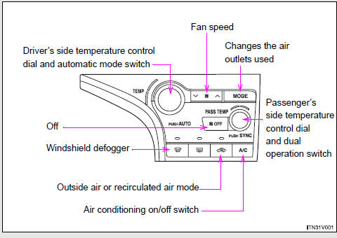
► Control panel
► Multi-information display (TFT type)
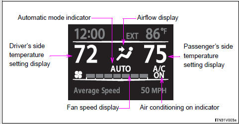
The settings display will differ according to the situation. If
 is pressed while in automatic mode,
the status of all settings will be displayed for a number of seconds.
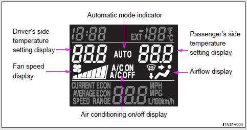
► Multi-information display (LCD type)
- Using the automatic mode
- Adjusting the settings
- Defogging the windshield
- Adjusting the position and opening and closing the air outlets

 Using the automatic mode
Press
.
The air conditioning system will begin to operate. In outside air or recirculated
air mode, air outlets, fan speed and air conditioning on/ off are automatically
adjusted according to ...
Other materials about Toyota Venza:
Open or Short Circuit in ABS Solenoid Relay Circuit (C0278/11)
DESCRIPTION
The ABS solenoid relay supplies power to the ABS solenoid and TRAC solenoid.
The solenoid relay is turned on 1.5 seconds after the ignition switch is turned
to ON, and is turned off if an open or short in the solenoid is detected by self
diag ...
Light Control Switch Circuit
DESCRIPTION
The main body ECU (driver side junction block assembly) receives the following
switch information:
Light control switch position off, tail, head or AUTO
Dimmer switch position high, low or high flash (pass)
Fog light switch posit ...
Removal
REMOVAL
PROCEDURE
1. DISCONNECT CABLE FROM NEGATIVE BATTERY TERMINAL
CAUTION:
Wait at least 90 seconds after disconnecting the cable from the negative (-)
battery terminal to disable the SRS system.
NOTICE:
When disconnecting the cable, some systems ne ...

0.1543