Toyota Venza: Installation
INSTALLATION
PROCEDURE
1. INSTALL POWER STEERING ECU ASSEMBLY
|
(a) Engage the 4 wire harness clamps to the power steering ECU assembly. |
|
.png)
|
(b) Install the power steering ECU assembly with the 3 nuts. Torque: 14 N·m {138 kgf·cm, 10 ft·lbf} |
|
.png)
|
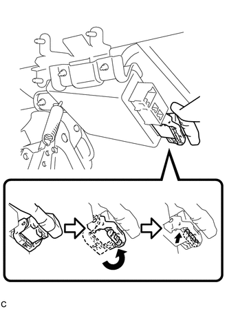
(c) Securely connect the connector to the power steering ECU assembly. HINT: Return the lock lever to its original position to connect the connector, and then securely push in the lock of the lock lever as shown in the illustration . |
|
|
(d) Connect the 3 connectors to the power steering ECU assembly. |
|
.png)
2. INSTALL DRIVER SIDE JUNCTION BLOCK ASSEMBLY
|
(a) Engage the 2 claws to install the driver side junction block assembly. |
|
.png)
(b) Connect the connectors to the back of the driver side junction block assembly.
|
(c) Install the driver side junction block assembly with the 3 nuts. Torque: 8.0 N·m {82 kgf·cm, 71 in·lbf} |
|
.png)
(d) Connect the connectors to the driver side junction block assembly.
3. INSTALL DRIVER SIDE KNEE AIRBAG ASSEMBLY
HINT:
Refer to the instructions for Installation of the knee airbag assembly (See page
.gif) ).
).
4. CONNECT CABLE TO NEGATIVE BATTERY TERMINAL
NOTICE:
When disconnecting the cable, some systems need to be initialized after the cable
is reconnected (See page ).
5. INITIALIZE ROTATION ANGLE SENSOR AND CALIBRATE TORQUE SENSOR ZERO POINT
(a) If replacing the power steering ECU assembly, clear the rotation angle sensor
calibration value, initialize the rotation angle sensor, and calibrate the torque
sensor zero point (See page ).
 Removal
REMOVAL
CAUTION / NOTICE / HINT
CAUTION:
Some of these service operations affect the SRS airbag system. Read the precautionary
notices concerning the SRS airbag system before servicing (See page
...

Other materials about Toyota Venza:
ECM Power Source Circuit
DESCRIPTION
When the ignition switch is turned to ON, the battery voltage is applied to IGSW
of the ECM. The output signal from the MREL terminal of the ECM causes a current
to flow to the coil, closing the contact of the engine room junction block assemb ...
Data Signal Circuit between Navigation Receiver Assembly and Stereo Jack Adapter
DESCRIPTION
The No. 1 stereo jack adapter assembly sends the sound data signal or image data
signal from a USB device to the navigation receiver assembly via this circuit.
WIRING DIAGRAM
PROCEDURE
1.
CHECK HARNESS AND CONNECTOR ( ...
Inspection
INSPECTION
PROCEDURE
1. INSPECT PARK/NEUTRAL POSITION SWITCH ASSEMBLY
(a) Measure the resistance according to the value(s) in the table below
when the shift lever is moved to each position.
Text in Illustration
*1
...

0.1785