Toyota Venza: Removal
REMOVAL
CAUTION / NOTICE / HINT
CAUTION:
Some of these service operations affect the SRS airbag system. Read the precautionary
notices concerning the SRS airbag system before servicing (See page
.gif) ).
).
NOTICE:
Be sure to read "Precaution" thoroughly before servicing (See page
).
PROCEDURE
1. PLACE FRONT WHEELS FACING STRAIGHT AHEAD
2. DISCONNECT CABLE FROM NEGATIVE BATTERY TERMINAL
CAUTION:
Wait at least 90 seconds after disconnecting the cable from the negative (-) battery terminal to disable the SRS system.
NOTICE:
When disconnecting the cable, some systems need to be initialized after the cable
is reconnected (See page ).
3. REMOVE DRIVER SIDE KNEE AIRBAG ASSEMBLY
HINT:
Refer to the instructions for Removal of the knee airbag assembly (See page
).
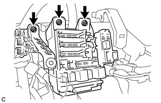
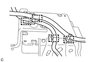
4. REMOVE DRIVER SIDE JUNCTION BLOCK ASSEMBLY
(a) Separate the wire harness clamp from the driver side junction block assembly.
(b) Disconnect the connectors from the driver side junction block assembly.
|
(c) Remove the 3 nuts. |
|
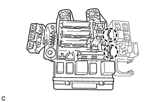
(d) Disconnect the connectors from the back of the driver side junction block assembly.
|
(e) Disengage the 2 claws to remove the driver side junction block assembly. |
|
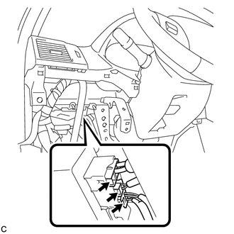
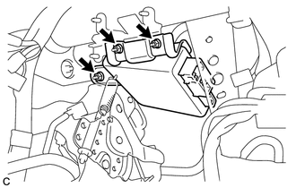
5. REMOVE POWER STEERING ECU ASSEMBLY
|
(a) Disconnect the 3 connectors from the power steering ECU assembly. |
|
|
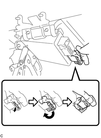
(b) Disconnect the connector from the power steering ECU assembly. HINT: Pull out the lock of the lock lever, disengage the claw, and raise the lock lever to disconnect the connector as shown in the illustration. |
|
|
(c) Remove the 3 nuts and power steering ECU assembly. |
|
|
(d) Disengage the 4 wire harness clamps from the power steering ECU assembly |
|
 Components
COMPONENTS
ILLUSTRATION
ILLUSTRATION
...
 Installation
INSTALLATION
PROCEDURE
1. INSTALL POWER STEERING ECU ASSEMBLY
(a) Engage the 4 wire harness clamps to the power steering ECU assembly.
...
Other materials about Toyota Venza:
On-vehicle Inspection
ON-VEHICLE INSPECTION
PROCEDURE
1. INSPECT FOR COOLANT LEAK
HINT:
The sliding surface inside the engine water pump assembly is lubricated
by engine coolant. As some engine coolant is discharged during normal operation,
engine coolant residu ...
Turn Signal Flasher Assembly
Components
COMPONENTS
ILLUSTRATION
Inspection
INSPECTION
PROCEDURE
1. INSPECT TURN SIGNAL FLASHER ASSEMBLY
(a) Disconnect the D34 turn signal flasher assembly connector.
(b) Measure the vo ...
Diagnosis System
DIAGNOSIS SYSTEM
1. DESCRIPTION
(a) Push-button start function data and the Diagnostic Trouble Codes (DTCs) can
be read through the Data Link Connector 3 (DLC3) of the vehicle. When the function
seems to be malfunctioning, use the Techstream to check for ...

0.1321