Toyota Venza: Inspection
INSPECTION
PROCEDURE
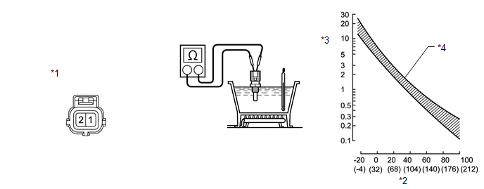
1. INSPECT ENGINE COOLANT TEMPERATURE SENSOR
 Text in Illustration
|
*1 |
Component without harness connected (Engine Coolant Temperature Sensor) |
*2 |
Temperature °C (°F) |
|
*3 |
Resistance Ω |
*4 |
Acceptable |
(a) Partially immerse the sensor in water and warm up the water.
(b) Measure the resistance according to the value(s) in the table below.
Standard Resistance:
|
Tester Connection |
Condition |
Specified Condition |
|---|---|---|
|
1 - 2 |
20°C (68°F) |
2.32 to 2.59 kΩ |
|
1 - 2 |
80°C (176°F) |
0.310 to 0.326 kΩ |
NOTICE:
When checking the sensor in water, keep the terminals dry. After the check, wipe the sensor dry.
If the result is not as specified, replace the engine coolant temperature sensor.
 Components
COMPONENTS
ILLUSTRATION
ILLUSTRATION
ILLUSTRATION
...
 Removal
REMOVAL
PROCEDURE
1. REMOVE NO. 1 ENGINE UNDER COVER
2. REMOVE NO. 2 ENGINE UNDER COVER
3. REMOVE WINDSHIELD WIPER MOTOR AND LINK
(a) Remove the windshield wiper motor and link (See page
).
4. ...
Other materials about Toyota Venza:
Power Back Door Main Switch
Components
COMPONENTS
ILLUSTRATION
Inspection
INSPECTION
PROCEDURE
1. INSPECT POWER BACK DOOR MAIN SWITCH
(a) Check that the switch function.
(1) Measure the resistance according to the value(s) in the table below.
Standard Resistance:
...
Engine compartment
► 2GR-FE engine
1. Engine coolant reservoir
2. Engine oil filler cap
3. Engine oil level dipstick
4. Brake fluid reservoir
5. Battery
6. Fuse box
7. Electric cooling fans
8. Condenser
9. Radiator
10.Washer fluid tank
► 1AR-FE engine
...
Input / Turbine Speed Sensor Circuit Malfunction (P0715,P0717)
DESCRIPTION
This sensor detects the rotation speed of the turbine which shows the input revolution
(speed) of the transaxle. By comparing the input turbine speed signal (NT) with
the counter gear speed sensor signal (NC), the TCM detects the shift timing ...

0.1338