Toyota Venza: Removal
REMOVAL
PROCEDURE
1. REMOVE NO. 1 ENGINE UNDER COVER
2. REMOVE NO. 2 ENGINE UNDER COVER
3. REMOVE WINDSHIELD WIPER MOTOR AND LINK
(a) Remove the windshield wiper motor and link (See page
.gif) ).
).
4. REMOVE OUTER COWL TOP PANEL SUB-ASSEMBLY
5. DRAIN ENGINE COOLANT
6. REMOVE NO. 1 ENGINE COVER SUB-ASSEMBLY
7. REMOVE NO. 1 VACUUM SWITCHING VALVE ASSEMBLY
8. REMOVE AIR CLEANER CAP SUB-ASSEMBLY
9. REMOVE AIR CLEANER FILTER ELEMENT SUB-ASSEMBLY
10. REMOVE AIR CLEANER CASE
11. REMOVE ENGINE COOLANT TEMPERATURE SENSOR
|
(a) Disconnect the engine coolant temperature sensor connector. Text in Illustration
|
|
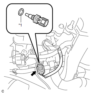
(b) Remove the engine coolant temperature sensor and gasket.
 Inspection
INSPECTION
PROCEDURE
1. INSPECT ENGINE COOLANT TEMPERATURE SENSOR
Text in Illustration
*1
Component without harness connected
(Engine Coolant Temperature Sensor)
...
 Installation
INSTALLATION
PROCEDURE
1. INSTALL ENGINE COOLANT TEMPERATURE SENSOR
(a) Install a new gasket to the sensor.
Text in Illustration
*1
New Gasket
...
Other materials about Toyota Venza:
Diagnosis System
DIAGNOSIS SYSTEM
1. DESCRIPTION
When troubleshooting OBD II (On-Board Diagnostics) vehicles, an OBD
II scan tool (complying with SAE J1987) must be connected to the DLC3 (Data
Link Connector 3) of the vehicle. Various data in the vehicle ECM ( ...
Disposal
DISPOSAL
CAUTION / NOTICE / HINT
CAUTION:
Before performing pre-disposal deployment of any SRS component, review and closely
follow all applicable environmental and hazardous material regulations. Pre-disposal
deployment may be considered hazardous mate ...
Front Passenger Side Power Mirror cannot be Adjusted with Power Mirror Switch
SYSTEM DESCRIPTION
When the mirror adjust switch is operated, the main body ECU (driver side junction
block assembly) detects the switch operation and sends the mirror adjust switch
signal to the outer mirror control ECU assembly (front passenger door) vi ...

0.1543