Toyota Venza: Knock Sensor 1 Circuit Low Input (Bank 1 or Single Sensor) (P0327,P0328)
DESCRIPTION
Flat-type knock sensors (non-resonant type) have structures that can detect vibrations between approximately 5 and 15 kHz.
Knock sensors are fitted onto the engine block to detect engine knocking.
The knock sensor contains a piezoelectric element which generates a voltage when it becomes deformed.
The voltage is generated when the engine block vibrates due to knocking. Any occurrence of engine knocking can be suppressed by delaying the ignition timing.
|
DTC No. |
DTC Detection Condition |
Trouble Area |
|---|---|---|
|
P0327 |
The output voltage of the knock sensor is below 0.5 V for 1 second or more (1 trip detection logic). |
|
|
P0328 |
The output voltage of the knock sensor is higher than 4.5 V for 1 second or more (1 trip detection logic). |
|
HINT:
When DTC P0327 or P0328 is stored, the ECM enters fail-safe mode. During fail-safe mode, the ignition timing is delayed to its maximum retardation. Fail-safe mode continues until the ignition switch is turned off.
Reference: Inspection using an oscilloscope
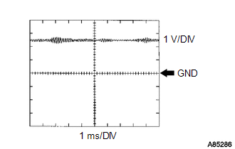
The correct waveform is as shown.
|
Terminal No. (Symbol) |
Tool Setting |
Condition |
|---|---|---|
|
B58-87 (KNK1) - B58-110 (EKNK) |
1 V/DIV, 1 ms/DIV |
Engine speed maintained at 4000 rpm after warming up engine |
MONITOR DESCRIPTION
If the output voltage transmitted by the knock sensor remains low or high for more than 1 second, the ECM interprets this as a malfunction in the sensor circuit, and stores a DTC.
The monitor for DTCs P0327 and P0328 begins to run when 5 seconds have elapsed since the engine was started.
MONITOR STRATEGY
|
Related DTCs |
P0327: Knock Sensor Range Check (Low Voltage) P0328: Knock Sensor Range Check (High Voltage) |
|
Required Sensors/Components (Main) |
Knock sensor |
|
Required Sensors/Components (Related) |
- |
|
Frequency of Operation |
Continuous |
|
Duration |
1 second |
|
MIL Operation |
Immediate |
|
Sequence of Operation |
None |
TYPICAL ENABLING CONDITIONS
|
Monitor runs whenever following DTCs not stored |
None |
|
All of the following conditions are met |
- |
|
Battery voltage |
10.5 V or higher |
|
Time after engine start |
5 seconds or more |
|
Ignition switch |
ON |
|
Starter |
OFF |
TYPICAL MALFUNCTION THRESHOLDS
P0327: Knock Sensor Range Check (Low Voltage)|
Knock sensor voltage |
Below 0.5 V |
|
Knock sensor voltage |
Higher than 4.5 V |
CONFIRMATION DRIVING PATTERN
- Connect the Techstream to the DLC3.
- Turn the ignition switch to ON and turn the Techstream on.
- Clear the DTCs (even if no DTCs are stored, perform the clear DTC procedure)
(See page
.gif) ).
). - Turn the ignition switch off and wait for at least 30 seconds.
- Turn the ignition switch to ON and turn the Techstream on.
- Start the engine and wait 5 seconds.
- Enter the following menus: Powertrain / Engine / Trouble Codes.
- Read the Pending DTCs.
HINT:
- If a pending DTC is output, the system is malfunctioning.
- If a pending DTC is not output, perform the following procedure.
- Enter the following menus: Powertrain / Engine / Utility / All Readiness.
- Input the DTC: P0327 or P0328.
- Check the DTC judgment result.
Techstream Display
Description
NORMAL
- DTC judgment completed
- System normal
ABNORMAL
- DTC judgment completed
- System abnormal
INCOMPLETE
- DTC judgment not completed
- Perform driving pattern after confirming DTC enabling conditions
N/A
- Unable to perform DTC judgment
- Number of DTCs which do not fulfill DTC preconditions has reached ECU memory limit
HINT:
- If the judgment result shows NORMAL, the system is normal.
- If the judgment result shows ABNORMAL, the system has a malfunction.
- If the judgment result shows INCOMPLETE or N/A, idle the engine for 5 minutes and check the DTC judgment result again.
- If no pending DTC is output, perform a universal trip and check for
permanent DTCs (See page ).
HINT:
- If a permanent DTC is output, the system is malfunctioning.
- If no permanent DTC is output, the system is normal.
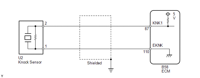
WIRING DIAGRAM
CAUTION / NOTICE / HINT
HINT:
Read freeze frame data using the Techstream. The ECM records vehicle and driving condition information as freeze frame data the moment a DTC is stored. When troubleshooting, freeze frame data can help determine if the vehicle was moving or stationary, if the engine was warmed up or not, if the air fuel ratio was lean or rich, and other data from the time the malfunction occurred.
PROCEDURE
|
1. |
READ VALUE USING TECHSTREAM (KNOCK FEEDBACK VALUE) |
(a) Connect the Techstream to the DLC3.
(b) Start the engine.
(c) Turn the Techstream on.
(d) Warm up the engine.
(e) Enter the following menus: Powertrain / Engine / Data List / Knock Feedback Value.
(f) Read the value while driving the vehicle.
OK:
The value changes.
|
Malfunction does not occur |
Knock Feedback Value changes |
|
Malfunctions occur |
Knock Feedback Value does not change |
HINT:
The knock feedback value change can be confirmed by running the engine with a high load, for example, by activating the air conditioning system and racing the engine.
| OK | .gif) |
CHECK FOR INTERMITTENT PROBLEMS |
|
.gif)
|
2. |
INSPECT ECM (KNK1 VOLTAGE) |
|
(a) Disconnect the knock sensor connector. |
|
(b) Turn the ignition switch to ON.
(c) Measure the voltage according to the value(s) in the table below.
Standard Voltage:
|
Tester Connection |
Switch Condition |
Specified Condition |
|---|---|---|
|
U2-2 - U2-1 |
Ignition switch ON |
4.5 to 5.5 V |
|
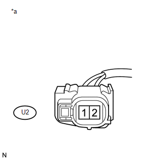
*a |
Front view of wire harness connector (to Knock Sensor) |
| NG | |
GO TO STEP 4 |
|
|
3. |
INSPECT KNOCK SENSOR |
(a) Inspect the knock control sensor (See page
).
HINT:
Perform "Inspection After Repair" after replacing the knock sensor (See page
).
| OK | |
REPLACE ECM |
| NG | |
REPLACE KNOCK SENSOR |
|
4. |
CHECK HARNESS AND CONNECTOR (ECM - KNOCK SENSOR) |
(a) Disconnect the knock sensor connector.
(b) Disconnect the ECM connector.
(c) Measure the resistance according to the value(s) in the table below.
Standard Resistance (Check for Open):
|
Tester Connection |
Condition |
Specified Condition |
|---|---|---|
|
U2-2 - B58-87 (KNK1) |
Always |
Below 1 Ω |
|
U2-1 - B58-110 (EKNK) |
Always |
Below 1 Ω |
Standard Resistance (Check for Short):
|
Tester Connection |
Condition |
Specified Condition |
|---|---|---|
|
U2-2 or B58-87 (KNK1) - Body ground |
Always |
10 kΩ or higher |
| OK | |
REPLACE ECM |
| NG | |
REPAIR OR REPLACE HARNESS OR CONNECTOR |
 Random / Multiple Cylinder Misfire Detected (P0300-P0304)
DESCRIPTION
When the engine misfires, high concentrations of hydrocarbons (HC) enter the
exhaust gas. Extremely high hydrocarbon concentration levels can cause an increase
in exhaust emission lev ...
 Crankshaft Position Sensor "A" Circuit (P0335,P0339)
DESCRIPTION
The crankshaft position sensor system consists of a crank angle sensor plate
and a pickup coil.
The sensor plate has 34 teeth and is installed on the crankshaft. The pickup
coil is m ...
Other materials about Toyota Venza:
Problem Symptoms Table
PROBLEM SYMPTOMS TABLE
Use the table below to help determine the cause of problem symptoms. If multiple
suspected areas are listed, the potential causes of the symptoms are listed in order
of probability in the "Suspected Area" column of the tab ...
Slip Indicator Light Remains ON
DESCRIPTION
The skid control ECU is connected to the combination meter via CAN communication.
The slip indicator light blinks during VSC and/or TRAC operation.
When the system fails, the slip indicator light comes on to warn the driver (See
page ).
WIRI ...
SRS airbags
The SRS airbags inflate when the vehicle is subjected to certain types of
severe impacts that may cause significant injury to the occupants. They work together
with the seat belts to help reduce the risk of death or serious injury.
► Front airbags ...

0.1126