Toyota Venza: Components
COMPONENTS
ILLUSTRATION
ILLUSTRATION
ILLUSTRATION

ILLUSTRATION
ILLUSTRATION

 Removal
REMOVAL
PROCEDURE
1. REMOVE FRONT SEAT ASSEMBLY LH
(See page )
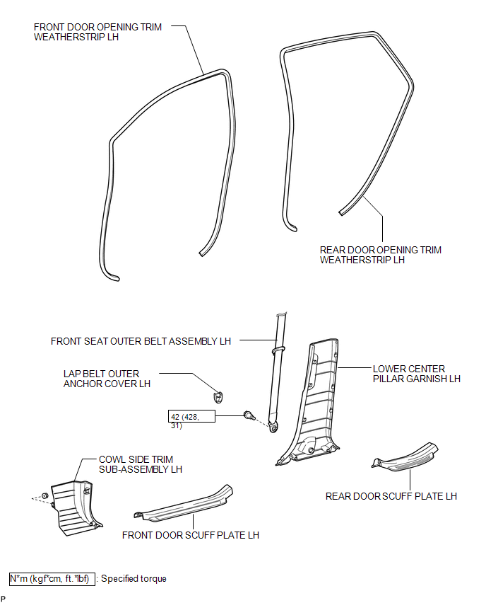
2. REMOVE FRONT DOOR SCUFF PLATE LH
3. REMOVE COWL SIDE TRIM SUB-ASSEMBLY LH
4. REMOVE FRONT DOOR OPENING TRIM WEATHERSTRIP ...
Other materials about Toyota Venza:
Dtc Check / Clear
DTC CHECK / CLEAR
1. DTC CHECK USING TECHSTREAM
(a) Connect the Techstream to the DLC3.
(b) Turn the ignition switch to ON.
(c) Turn the Techstream on.
(d) Enter the following menus: Body / Air Conditioner / DTC.
(e) Check for DTCs.
2. DTC CLEAR USING T ...
Data List / Active Test
DATA LIST / ACTIVE TEST
1. DATA LIST
HINT:
Using the Techstream to read the Data List allows the values or states of switches,
sensors, actuators and other items to be read without removing any parts. This non-intrusive
inspection can be very useful bec ...
Transfer Oil
On-vehicle Inspection
ON-VEHICLE INSPECTION
PROCEDURE
1. INSPECT TRANSFER OIL
(a) Remove the No. 1 transfer case plug and gasket.
(b) Check that the oil level is between 0 and 5 mm (0 ...

0.1265