Toyota Venza: Components
COMPONENTS
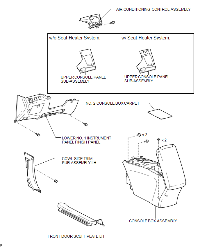
ILLUSTRATION
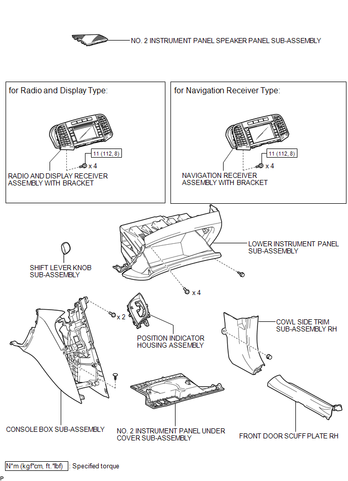
ILLUSTRATION
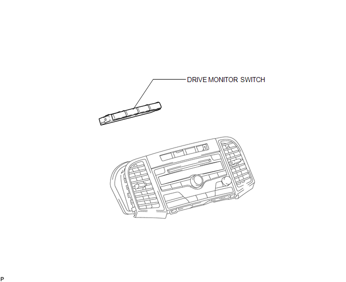
ILLUSTRATION

 Inspection
INSPECTION
PROCEDURE
1. INSPECT DRIVE MONITOR SWITCH
(a) Measure the resistance according to the value(s) in the table below.
Standard Resistance:
Tester Connecti ...
Other materials about Toyota Venza:
Driving position memory
Your preferred driving position (the position of the driver’s seat and angle
of the outside rear view mirrors) can be memorized and recalled by pressing a button.
It is also possible to set this function to activate automatically when the doors
are unl ...
Calibration
CALIBRATION
1. ROTATION ANGLE SENSOR INITIALIZATION AND TORQUE SENSOR ZERO POINT CALIBRATION
NOTICE:
Clear the rotation angle sensor calibration value, initialize the rotation angle
sensor, and calibrate the torque sensor zero point if any of the followin ...
Inspection
INSPECTION
PROCEDURE
1. INSPECT PRELOAD
(a) Using SST and a torque wrench, measure the preload of the backlash
between the driven pinion and ring gear.
SST: 09326-20011
Preload (at Starting):
Item
P ...

0.1649