Toyota Venza: Inspection
INSPECTION
PROCEDURE
1. INSPECT TIE ROD ASSEMBLY LH
|
(a) Secure the tie rod assembly LH in a vise. |
|
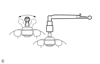
(b) Install the nut to the stud bolt.
(c) Flip the ball joint back and forth 5 times.
(d) Set a torque wrench to the nut, turn the ball joint continuously at a rate of 2 to 4 seconds per turn, and check the turning torque on the 5th turn.
Standard turning torque:
0.49 to 3.43 N*m (5.0 to 35.0 kgf*cm, 4.3 to 30.3 in.*lbf)
HINT:
If the turning torque is not within the specified range, replace the tie rod assembly LH.
2. INSPECT TIE ROD ASSEMBLY RH
HINT:
Perform the same procedure as for the LH side.
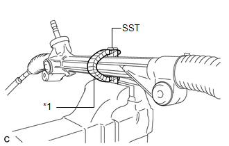
3. INSPECT TOTAL PRELOAD
|
(a) Using SST, secure the steering link assembly in a vise. SST: 09612-00012 Text in Illustration
HINT: Tape SST before use. |
|
|
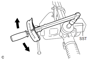
(b) Using SST and a torque wrench, inspect the total preload. SST: 09616-00020 Standard preload: 0.7 to 1.0 N*m (7.0 to 10.7 kgf*cm, 5.8 to 9.2 in.*lbf) NOTICE: Inspect the total preload around the steering rack center position. HINT: If the total preload is not within the specified range, replace the steering gear assembly with a new one. |
|
 Disassembly
DISASSEMBLY
PROCEDURE
1. REMOVE STEERING RACK BOOT CLIP (for LH Side)
(a) Using pliers, remove the steering rack boot clip.
2. REMOVE STEERING RACK BOOT CLIP (for RH Side)
HINT:
Perform the same ...
 Installation
INSTALLATION
CAUTION / NOTICE / HINT
NOTICE:
When disconnecting the steering intermediate shaft assembly and pinion shaft
of steering gear assembly, be sure to place matchmarks before servicing.
...
Other materials about Toyota Venza:
How To Proceed With Troubleshooting
CAUTION / NOTICE / HINT
HINT:
Use the following procedure to troubleshoot the front power seat control
system (w/ Memory).
*: Use the Techstream.
PROCEDURE
1.
VEHICLE BROUGHT TO WORKSHOP
...
Components
COMPONENTS
ILLUSTRATION
ILLUSTRATION
ILLUSTRATION
ILLUSTRATION
ILLUSTRATION
ILLUSTRATION
ILLUSTRATION
ILLUSTRATION
ILLUSTRATION
...
Problem Symptoms Table
PROBLEM SYMPTOMS TABLE
HINT:
Use the table below to help determine the cause of problem symptoms.
If multiple suspected areas are listed, the potential causes of the symptoms
are listed in order of probability in the "Suspected Area" ...

0.1248