Toyota Venza: Back Door cannot be Opened
DESCRIPTION
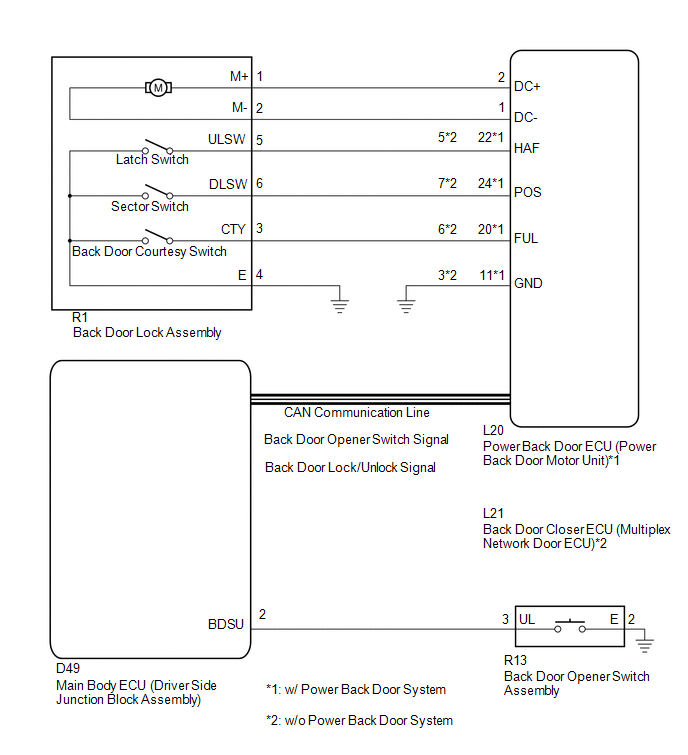
When the back door cannot be opened, one of the following may be malfunctioning: 1) power back door ECU (power back door motor unit)*1 or back door closer ECU (multiplex network door ECU)*2, 2) back door lock assembly, 3) back door opener switch assembly, or 4) main body ECU (driver side junction block assembly).
- *1: w/ Power Back Door System
- *2: w/o Power Back Door System
WIRING DIAGRAM
CAUTION / NOTICE / HINT
NOTICE:
The back door closer system uses CAN communication. First, follow "How to Proceed with Troubleshooting" and at step "Check Communication Function of CAN Communication System", confirm that there is no malfunction in the CAN communication system. After confirming that B2250 or B2251 is not output, proceed with troubleshooting.
PROCEDURE
|
1. |
READ VALUE USING TECHSTREAM |
(a) Connect the Techstream to the DLC3.
(b) Turn the ignition switch to ON.
(c) Turn the Techstream on.
(d) Enter the following menus: Body Electrical / Main Body / Data List.
(e) Check if the back door lock functions properly.
Main Body (Main Body ECU (Driver Side Junction Block Assembly))|
Tester Display |
Measurement Item/Range |
Normal Condition |
Diagnostic Note |
|---|---|---|---|
|
Back Door Open |
Back door lock / Permit or Prohibit |
Permit: Back door unlocked Prohibit: Back door locked |
- |
OK:
The back door functions as specified in the normal condition column.
| NG | .gif) |
REPLACE MAIN BODY ECU (DRIVER SIDE JUNCTION BLOCK ASSEMBLY) |
|
.gif)
|
2. |
READ VALUE USING TECHSTREAM |
(a) Connect the Techstream to the DLC3.
(b) Turn the ignition switch to ON.
(c) Turn the Techstream on.
(d) Enter the following menus: Body Electrical / Back Door / Data List.
(e) Check if the back door lock functions properly.
Back Door (Power Back Door ECU*1 or Back Door Closer ECU*2)|
Tester Display |
Measurement Item/Range |
Normal Condition |
Diagnostic Note |
|---|---|---|---|
|
Door Lock Status |
Back door lock condition signal / LOCK or UNLOCK |
LOCK: Back door locked UNLOCK: Back door unlocked |
- |
- *1: w/ Power Back Door System
- *2: w/o Power Back Door System
OK:
The back door functions as specified in the normal condition column.
|
Result |
Proceed to |
|---|---|
|
OK |
A |
|
NG (w/ Power Back Door ECU) |
B |
|
NG (w/o Power Back Door ECU) |
C |
| B | |
REPLACE POWER BACK DOOR ECU (POWER BACK DOOR MOTOR UNIT) |
| C | |
REPLACE BACK DOOR CLOSER ECU (MULTIPLEX NETWORK DOOR ECU) |
|
|
3. |
READ VALUE USING TECHSTREAM |
(a) Connect the Techstream to the DLC3.
(b) Turn the ignition switch to ON.
(c) Turn the Techstream on.
(d) Enter the following menus: Body Electrical / Main Body / Data List.
(e) Check if the switch functions properly.
Main Body (Main Body ECU (Driver Side Junction Block Assembly))|
Tester Display |
Measurement Item/Range |
Normal Condition |
Diagnostic Note |
|---|---|---|---|
|
Back Door Open Handle SW |
Back door opener switch / ON or OFF |
ON: Back door opener switch pushed OFF: Back door opener switch not pushed |
- |
OK:
The back door opener switch functions as specified in the normal condition column.
| NG | |
GO TO STEP 6 |
|
|
4. |
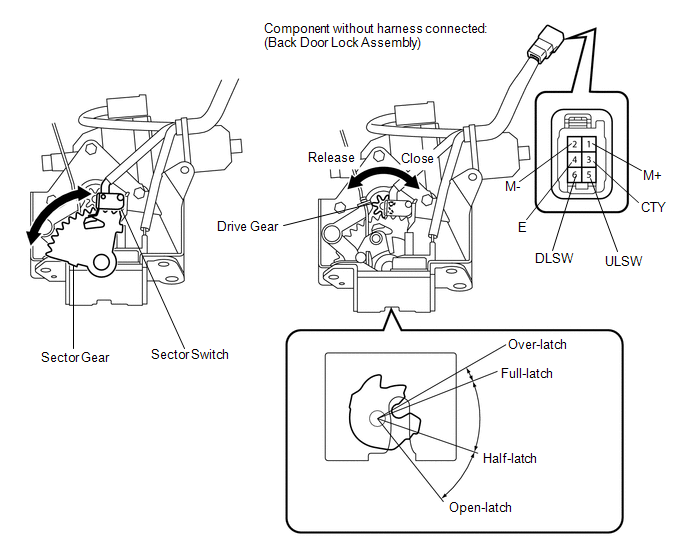
INSPECT BACK DOOR LOCK ASSEMBLY |
(a) Remove the back door lock assembly (See page
.gif) ).
).
(b) Apply battery voltage and check the operation of the door lock motor.
OK:
|
Measurement Condition |
Specified Condition |
|---|---|
|
Battery positive (+) → Terminal 1 (M+) Battery negative (-) → Terminal 2 (M-) |
Latch turns to full-latch position |
|
Battery positive (+) → Terminal 2 (M-) Battery negative (-) → Terminal 1 (M+) |
Latch turns to open-latch position |
(c) Measure the resistance according to the value(s) in the table below.
Standard Resistance:
Latch Switch|
Tester Connection |
Condition |
Specified Condition |
|---|---|---|
|
5 (ULSW) - 4 (E) |
Open-latch |
Below 1 Ω |
|
5 (ULSW) - 4 (E) |
Half-latch |
10 kΩ or higher |
|
5 (ULSW) - 4 (E) |
Full-latch |
10 kΩ or higher |
|
5 (ULSW) - 4 (E) |
Over-latch |
Below 1 Ω |
|
Tester Connection |
Condition |
Specified Condition |
|---|---|---|
|
6 (DLSW) - 4 (E) |
Sector gear in neutral position (Sector switch on) |
Below 1 Ω |
|
6 (DLSW) - 4 (E) |
Sector gear not in neutral position (Sector switch off) |
10 kΩ or higher |
|
Tester Connection |
Condition |
Specified Condition |
|---|---|---|
|
3 (CTY) - 4 (E) |
Open-latch |
Below 1 Ω |
|
3 (CTY) - 4 (E) |
Half-latch |
Below 1 Ω |
|
3 (CTY) - 4 (E) |
Full-latch |
10 kΩ or higher |
|
3 (CTY) - 4 (E) |
Over-latch |
10 kΩ or higher |
| NG | |
REPLACE BACK DOOR LOCK ASSEMBLY |
|
|
5. |
CHECK HARNESS AND CONNECTOR (BACK DOOR LOCK ASSEMBLY - POWER BACK DOOR ECU OR BACK DOOR CLOSER ECU) |
(a) w/ Power Back Door System
(1) Disconnect the R1 back door lock assembly connector and L20 power back door ECU connector.
(2) Measure the resistance according to the value(s) in the table below.
Standard Resistance:
|
Tester Connection |
Condition |
Specified Condition |
|---|---|---|
|
R1-1 (M+) - L20-2 (DC+) |
Always |
Below 1 Ω |
|
R1-2 (M-) - L20-1 (DC-) |
Always |
Below 1 Ω |
|
R1-5 (ULSW) - L20-22 (HAF) |
Always |
Below 1 Ω |
|
R1-6 (DLSW) - L20-24 (POS) |
Always |
Below 1 Ω |
|
R1-3 (CTY) - L20-20 (FUL) |
Always |
Below 1 Ω |
|
R1-4 (E) - Body ground |
Always |
Below 1 Ω |
|
R1-1 (M+) - Body ground |
Always |
10 kΩ or higher |
|
R1-2 (M-) - Body ground |
Always |
10 kΩ or higher |
|
R1-5 (ULSW) - Body ground |
Always |
10 kΩ or higher |
|
R1-6 (DLSW) - Body ground |
Always |
10 kΩ or higher |
|
R1-3 (CTY) - Body ground |
Always |
10 kΩ or higher |
|
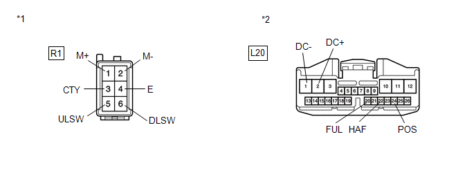
*1 |
Front view of wire harness connector (to Back Door Lock) |
|
*2 |
Front view of wire harness connector (to Power Back Door ECU) |
|
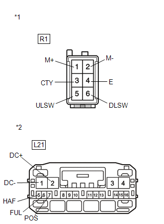
(b) w/o Power Back Door System (1) Disconnect the R1 back door lock assembly connector and L21 back door closer ECU connector. (2) Measure the resistance according to the value(s) in the table below. Standard Resistance:
|
|
|
Result |
Proceed to |
|---|---|
|
NG |
A |
|
OK (w/ Power Back Door System) |
B |
|
OK (w/o Power Back Door System) |
C |
| A | |
REPAIR OR REPLACE HARNESS OR CONNECTOR |
| B | |
REPLACE POWER BACK DOOR ECU (POWER BACK DOOR MOTOR UNIT) |
| C | |
REPLACE BACK DOOR CLOSER ECU (MULTIPLEX NETWORK DOOR ECU) |
|
6. |
INSPECT BACK DOOR OPENER SWITCH ASSEMBLY |
(a) Remove the back door opener switch assembly (See page
).
(b) Measure the resistance according to the value(s) in the table below.
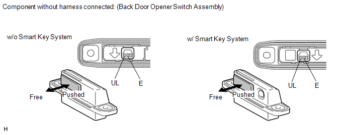
Standard Resistance:
|
Tester Connection |
Condition |
Specified Condition |
|---|---|---|
|
2 (E) - 3 (UL) |
Back door opener switch not pushed (off) |
10 kΩ or higher |
|
2 (E) - 3 (UL) |
Back door opener switch pushed (on) |
Below 1 Ω |
| NG | |
REPLACE BACK DOOR OPENER SWITCH ASSEMBLY |
|
|
7. |
CHECK HARNESS AND CONNECTOR (BACK DOOR OPENER SWITCH ASSEMBLY - MAIN BODY ECU) |
(a) Disconnect the R13 back door opener switch assembly connector and D49 main body ECU connector.
|
(b) Measure the resistance according to the value(s) in the table below. Standard Resistance:
|
|
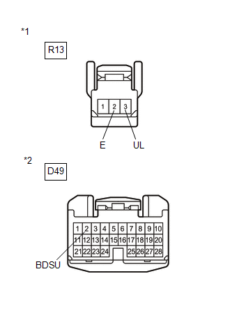
| OK | |
REPLACE MAIN BODY ECU (DRIVER SIDE JUNCTION BLOCK ASSEMBLY) |
| NG | |
REPAIR OR REPLACE HARNESS OR CONNECTOR |
 Back Door Closer Operation Malfunction (B2250)
DESCRIPTION
The power back door ECU (power back door motor unit)*1 or back door closer ECU
(multiplex network door ECU)*2 receives signals from the latch switch, sector switch
and back door court ...
 Back Door Closer does not Operate
DESCRIPTION
When the back door closer does not operate, one of the following may be the cause:
1) improper fit of the back door, or a foreign object is stuck in the back door
or 2) initialization ...
Other materials about Toyota Venza:
Power Mirrors do not Return to Memorized Position
SYSTEM DESCRIPTION
If either the M1 or M2 seat memory switch is pressed, the outer mirror control
ECU assembly (driver door) detects the seat memory switch status and sends the switch
signal to the main body ECU (driver side junction block assembly) via C ...
IG2 Signal Malfunction (B2788)
DESCRIPTION
The steering lock ECU (steering lock actuator assembly) receives power from the
IG2 relay. When the voltage value indicated by the IG signal from the certification
ECU (smart key ECU assembly) equals to the voltage that is applied to the steer ...
Washer Motor(for Front Side)
Components
COMPONENTS
ILLUSTRATION
Removal
REMOVAL
PROCEDURE
1. REMOVE FRONT WHEEL RH
2. REMOVE FRONT FENDER OUTSIDE MOULDING RH
HINT:
Use the same procedure for the RH side and LH side (See page
).
3. REMOVE FRONT FENDER LINER RH
...

0.1618