Toyota Venza: System Description
SYSTEM DESCRIPTION
1. DESCRIPTION OF OCCUPANT CLASSIFICATION SYSTEM
(a) GENERAL DESCRIPTION
(1) In the occupant classification system, the occupant classification ECU calculates the weight of the occupant based on signals from the occupant classification sensors. This system recognizes the occupant as a child if it detects a weight of less than 32 kg (70.6 lb), and disables the front passenger airbag and front seat belt pretensioner RH.
(2) This system is mainly comprised of 4 occupant classification sensors that detect the load on the front passenger seat. The occupant classification ECU controls the system, and the passenger airbag ON/OFF indicator indicates the ON/OFF condition of the front passenger airbag and front seat belt pretensioner RH.
(b) OCCUPANT CLASSIFICATION SENSOR
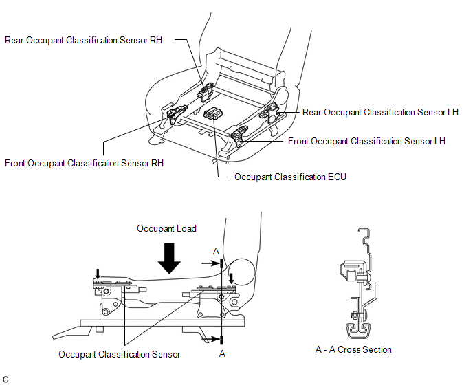
(1) The occupant classification sensors are installed on 4 brackets connecting the seat rail and seat frame. Accordingly, when load is applied to the front passenger seat by an occupant sitting in it, the occupant classification sensors register a distortion.
(c) DESCRIPTION FOR PASSENGER AIRBAG ON/OFF INDICATOR
.png)
(1) This indicator informs the driver whether the occupant classification ECU puts the front passenger airbag and front seat belt pretensioner RH into an active state or inactive state.
(2) If a malfunction occurs in the occupant classification system, the passenger airbag ON/OFF indicator ("OFF") and the SRS warning light come on.
 How To Proceed With Troubleshooting
CAUTION / NOTICE / HINT
HINT:
*: Use the Techstream
PROCEDURE
1.
VEHICLE BROUGHT TO WORKSHOP
NEXT
...
 Initialization
INITIALIZATION
NOTICE:
Make sure that the front passenger seat is not occupied before performing the
operation.
HINT:
Perform zero point calibration and sensitivity check if any of the following ...
Other materials about Toyota Venza:
Terminals Of Ecu
TERMINALS OF ECU
1. CHECK OUTER MIRROR CONTROL ECU ASSEMBLY (DRIVER DOOR)
(a) Disconnect the I13 connector.
(b) Measure the voltage and resistance according to the value(s) in the table
below.
HINT:
Measure the values on the wire harness side with the ...
Adjustment
ADJUSTMENT
PROCEDURE
1. ADJUST STEERING WHEEL OFF CENTER
(a) Inspect steering wheel off center.
(1) Apply masking tape on the top center of the steering wheel and steering
column upper cover.
Text in Illustration
*1
...
Operation Check
OPERATION CHECK
1. CHECK WINDOW LOCK SWITCH
HINT:
Before performing the window lock switch operation check, make sure that the
window lock switch is off (the switch is not pushed in).
(a) Check that the front passenger and rear windows cannot be operat ...

0.1596