Toyota Venza: Ignition Switch
Components
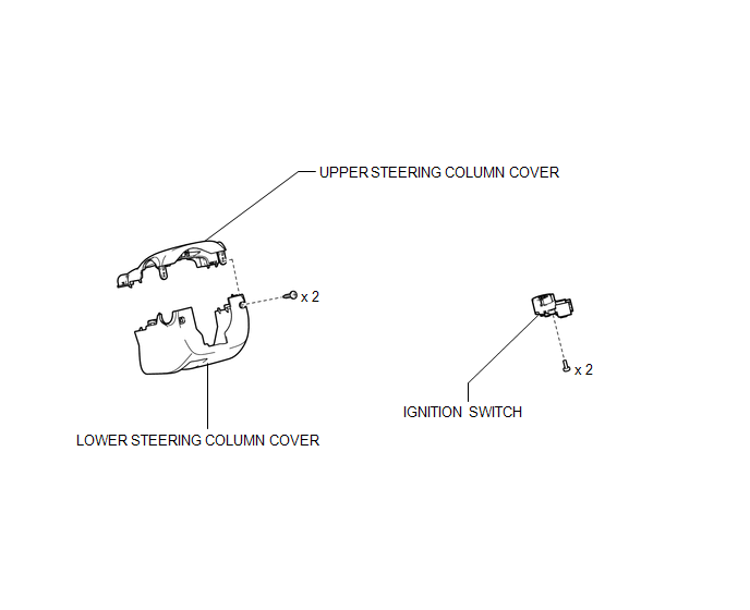
COMPONENTS
ILLUSTRATION
Removal
REMOVAL
PROCEDURE
1. REMOVE LOWER STEERING COLUMN COVER
.gif)
2. REMOVE UPPER STEERING COLUMN COVER
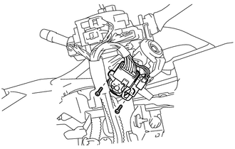
3. REMOVE IGNITION SWITCH
|
(a) Remove the 2 screws and ignition switch. |
|
|
(b) Disconnect the connector. |
|
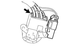
(c) Disconnect the connector clamp from the ignition switch.
Inspection
INSPECTION
PROCEDURE
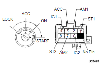
1. INSPECT IGNITION SWITCH
|
(a) Measure the switch resistance. Standard Resistance:
If the result is not as specified, replace the switch assembly. |
|
Installation
INSTALLATION
PROCEDURE
1. INSTALL IGNITION SWITCH
|
(a) Connect the connector. |
|
.png)
(b) Install the connector clamp to the ignition switch.
|
(c) Install the ignition switch with the 2 screws. |
|
.png)
2. INSTALL UPPER STEERING COLUMN COVER
.gif)
3. INSTALL LOWER STEERING COLUMN COVER
 Installation
INSTALLATION
PROCEDURE
1. INSTALL ENGINE SWITCH
(a) Attach the 2 claws to install the engine switch.
2. INSTALL LOWER INSTRUMENT PANEL FI ...
 Relay
Relay
On-vehicle Inspection
ON-VEHICLE INSPECTION
PROCEDURE
1. INSPECT STARTER RELAY
(a) Measure the resistance according to the value(s) in the table below.
Standard Resistance:
...
Other materials about Toyota Venza:
Diagnosis System
DIAGNOSIS SYSTEM
1. CHECK DLC3
(a) Check the DLC3 (See page ).
2. FUNCTION OF PASSENGER AIRBAG ON/OFF INDICATOR
(a) Initial check.
(1) Turn the ignition switch to ON.
(2) The passenger airbag ON/OFF indicator ("ON" and "OFF") comes o ...
Problem Symptoms Table
PROBLEM SYMPTOMS TABLE
HINT:
Use the table below to help determine the cause of problem symptoms. If multiple
suspected areas are listed, the potential causes of the symptoms are listed in order
of probability in the "Suspected Area" column of ...
Disassembly
DISASSEMBLY
PROCEDURE
1. REMOVE COOLER DRYER
(a) Using a 14 mm straight hexagon wrench, remove the cap from the modulator.
Text in Illustration
*1
14 mm Straight Hexagon Wrench
*2 ...

0.1223