Toyota Venza: Ignition Coil And Spark Plug
Components
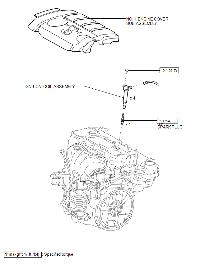
COMPONENTS
ILLUSTRATION
Removal
REMOVAL
PROCEDURE
1. REMOVE NO. 1 ENGINE COVER SUB-ASSEMBLY
.gif)
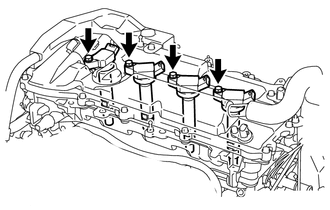
2. REMOVE IGNITION COIL ASSEMBLY
(a) Disconnect the 4 ignition coil assembly connectors.
|
(b) Remove the 4 bolts and 4 ignition coil assemblies. |
|
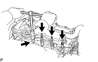
3. REMOVE SPARK PLUG
|
(a) Using a spark plug wrench, remove the 4 spark plugs. |
|
Installation
INSTALLATION
PROCEDURE
1. INSTALL SPARK PLUG
|
(a) Using a spark plug wrench, install the 4 spark plugs. Torque: 25 N·m {254 kgf·cm, 18 ft·lbf} HINT: Perform "Inspection After Repair" after replacing the spark plugs (See
page |
|
.png)
2. INSTALL IGNITION COIL ASSEMBLY
|
(a) Install the 4 ignition coil assemblies with the 4 bolts. Torque: 10 N·m {102 kgf·cm, 7 ft·lbf} HINT: Perform "Inspection After Repair" after replacing an ignition coil assembly
(See page |
|
.png)
(b) Connect the 4 ignition coil assembly connectors.
3. INSTALL NO. 1 ENGINE COVER SUB-ASSEMBLY
.gif)
 Heated Oxygen Sensor
Components
COMPONENTS
ILLUSTRATION
Removal
REMOVAL
PROCEDURE
1. REMOVE NO. 1 ENGINE UNDER COVER
2. REMOVE NO. 2 ENGINE UNDER COVER
3. REMOVE FRONT EXHAUST PIPE ASSEMBLY
4. REMOVE HEA ...
 Ignition System
...
Other materials about Toyota Venza:
Problem Symptoms Table
PROBLEM SYMPTOMS TABLE
NOTICE:
After replacing the stereo component tuner assembly of vehicles subscribed to
pay-type satellite radio broadcasts, XM radio ID registration is necessary (w/ SDARS
System).
HINT:
Use the table below to help determi ...
On-vehicle Inspection
ON-VEHICLE INSPECTION
PROCEDURE
1. CHECK POWER SOURCE MODE CHANGE FUNCTION
(a) Check the function of the engine switch.
(1) Check that power source mode changes in accordance with the conditions of
the shift position and brake pedal.
Brake Pe ...
Terminals Of Ecm
TERMINALS OF ECM
HINT:
The standard voltage between each pair of ECM terminals is shown in the table
below. The appropriate conditions for checking each pair of terminals are also indicated.
The result of checks should be compared with the standard vol ...

0.1578