Toyota Venza: Height Control Sensor
Components
COMPONENTS
ILLUSTRATION
ILLUSTRATION
Removal
REMOVAL
PROCEDURE
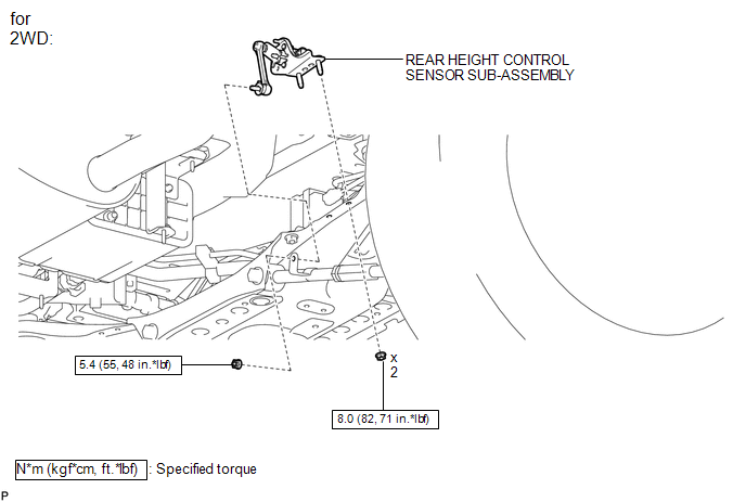
1. REMOVE REAR HEIGHT CONTROL SENSOR SUB-ASSEMBLY (for 2WD)
|
(a) Disconnect the connector. |
|
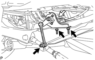
(b) Remove the 3 nuts and rear height control sensor sub-assembly.
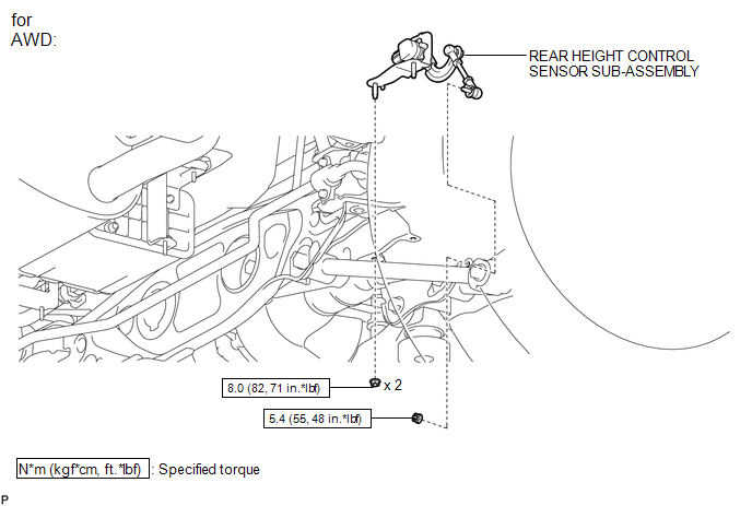
2. REMOVE REAR HEIGHT CONTROL SENSOR SUB-ASSEMBLY (for AWD)
|
(a) Disconnect the connector. |
|
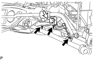
(b) Remove the 3 nuts and rear height control sensor sub-assembly.
Inspection
INSPECTION
PROCEDURE
1. INSPECT REAR HEIGHT CONTROL SENSOR SUB-ASSEMBLY RH (for 2WD)
|
(a) Connect 3 dry cell batteries (1.5 V) in series. |
|
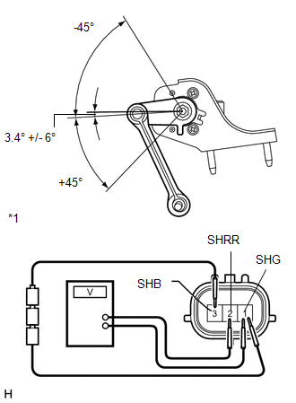
(b) Connect a positive (+) lead from the batteries to terminal 3 (SHB) and a negative (-) lead from the batteries to terminal 1 (SHG).
(c) Measure the voltage between terminals 2 (SHRR) and 1 (SHG) while slowly moving the link up and down.
Standard Voltage:
|
Tester Connection |
Condition |
Specified Condition |
|---|---|---|
|
2 (SHRR) - 1 (SHG) |
+45° (High) |
4.05 V |
|
2 (SHRR) - 1 (SHG) |
0° (normal) |
2.25 V |
|
2 (SHRR) - 1 (SHG) |
-45° (Low) |
0.45 V |
|
*1 |
Component without harness connected (Rear Height Control Sensor Sub-assembly RH) |
If the result is not as specified, replace the rear height control sensor sub-assembly RH.
2. INSPECT REAR HEIGHT CONTROL SENSOR SUB-ASSEMBLY RH (for AWD)
|
(a) Connect 3 dry cell batteries (1.5 V) in series. |
|
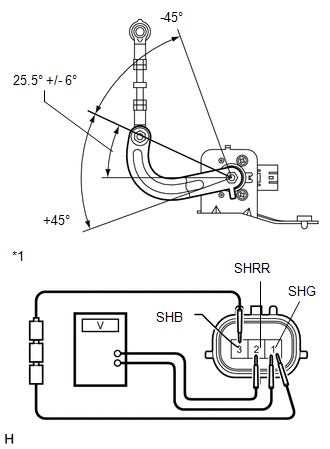
(b) Connect a positive (+) lead from the batteries to terminal 3 (SHB) and a negative (-) lead from the batteries to terminal 1 (SHG).
(c) Measure the voltage between terminals 2 (SHRR) and 1 (SHG) while slowly moving the link up and down.
Standard Voltage:
|
Tester Connection |
Condition |
Specified Condition |
|---|---|---|
|
2 (SHRR) - 1 (SHG) |
+45° (High) |
4.05 V |
|
2 (SHRR) - 1 (SHG) |
0° (normal) |
2.25 V |
|
2 (SHRR) - 1 (SHG) |
-45° (Low) |
0.45 V |
|
*1 |
Component without harness connected (Rear Height Control Sensor Sub-assembly RH) |
If the result is not as specified, replace the rear height control sensor sub-assembly RH.
Installation
INSTALLATION
PROCEDURE
1. INSTALL REAR HEIGHT CONTROL SENSOR SUB-ASSEMBLY (for 2WD)
|
(a) Install the rear height control sensor sub-assembly with the 3 nuts. Torque: Nut (A) : 8.0 N·m {82 kgf·cm, 71 in·lbf} Nut (B) : 5.4 N·m {55 kgf·cm, 48 in·lbf} |
|
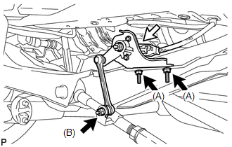
(b) Connect the connector.
2. INSTALL REAR HEIGHT CONTROL SENSOR SUB-ASSEMBLY (for AWD)
|
(a) Install the rear height control sensor sub-assembly with the 3 nuts. Torque: Nut (A) : 8.0 N·m {82 kgf·cm, 71 in·lbf} Nut (B) : 5.4 N·m {55 kgf·cm, 48 in·lbf} |
|
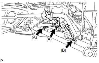
(b) Connect the connector.
3. HEIGHT CONTROL SENSOR SIGNAL INITIALIZATION
(See page .gif) )
)
4. PREPARE VEHICLE FOR HEADLIGHT AIM ADJUSTMENT
5. PREPARE FOR HEADLIGHT AIMING
6. INSPECT HEADLIGHT AIMING
7. ADJUST HEADLIGHT AIMING
 Headlight Leveling Ecu
Components
COMPONENTS
ILLUSTRATION
Removal
REMOVAL
PROCEDURE
1. REMOVE HEADLIGHT LEVELING ECU ASSEMBLY
(a) Disconnect the connector.
...

Other materials about Toyota Venza:
Poor Sound Quality in All Modes (Low Volume)
PROCEDURE
1.
CHECK AUDIO SETTINGS
(a) Set treble, middle and bass to the initial values and check that the sound
is normal.
OK:
The sound returns to normal.
HINT:
Sound quality adjustment measures vary according to the ...
Theft Deterrent System Presence Detection (B279C)
DESCRIPTION
If an ECM that is incompatible with the engine immobiliser system is installed,
the ECM stores this DTC.
DTC No.
DTC Detection Condition
Trouble Area
B279C
An ECM that is incompatible ...
Check CAN Bus Line for Short to GND
DESCRIPTION
There may be a short circuit between the CAN bus main wire and GND when there
is no resistance between terminals 6 (CANH) and 4 (CG) or 14 (CANL) and 4 (CG) of
the DLC3.
Symptom
Trouble Area
No resistanc ...

0.174