Toyota Venza: Headlight Leveling Ecu
Components
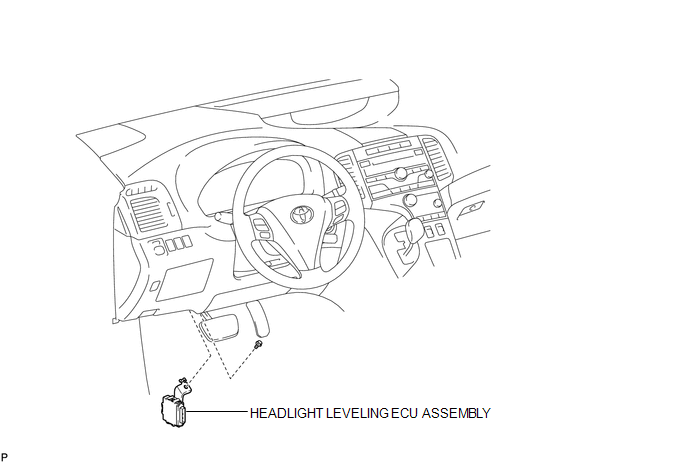
COMPONENTS
ILLUSTRATION
Removal
REMOVAL
PROCEDURE
1. REMOVE HEADLIGHT LEVELING ECU ASSEMBLY
|
(a) Disconnect the connector. |
|
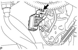
(b) Remove the bolt and headlight leveling ECU assembly.
Installation
INSTALLATION
PROCEDURE
1. INSTALL HEADLIGHT LEVELING ECU ASSEMBLY
|
(a) Install the headlight leveling ECU assembly with the bolt. |
|
.png)
(b) Connect the connector.
2. HEIGHT CONTROL SENSOR SIGNAL INITIALIZATION
(See page .gif) )
)
3. PREPARE VEHICLE FOR HEADLIGHT AIM ADJUSTMENT
4. PREPARE FOR HEADLIGHT AIMING
5. INSPECT HEADLIGHT AIMING
6. ADJUST HEADLIGHT AIMING
 Headlight Dimmer Switch
Components
COMPONENTS
ILLUSTRATION
Removal
REMOVAL
PROCEDURE
1. REMOVE SPIRAL CABLE WITH SENSOR SUB-ASSEMBLY
(See page )
2. REMOVE WINDSHIELD WIPER SWITCH ASSEMBLY
3. REMOVE HEADLIG ...
 Height Control Sensor
Components
COMPONENTS
ILLUSTRATION
ILLUSTRATION
Removal
REMOVAL
PROCEDURE
1. REMOVE REAR HEIGHT CONTROL SENSOR SUB-ASSEMBLY (for 2WD)
(a) Disconnect the connector.
...
Other materials about Toyota Venza:
Operation Check
OPERATION CHECK
1. SMART KEY SYSTEM OPERATION INSPECTION
(a) Check the entry unlock function.
(1) Use the wireless lock operation to lock the doors. With the key outside the
vehicle, touch a front door outside handle assembly (touch sensor) and check that ...
How To Proceed With Troubleshooting
CAUTION / NOTICE / HINT
HINT:
Use the following procedure to troubleshoot.
*: Use the Techstream.
PROCEDURE
1.
VEHICLE BROUGHT TO WORKSHOP
NEXT
...
Operation Check
OPERATION CHECK
1. CHECK AUTO OPERATION
NOTICE:
Make sure that initialization is completed before inspection (See page
).
HINT:
When pressing the switch for 0.3 seconds or less, the roof glass moves but auto
operation does not operate.
(a) Turn the i ...

0.1578