Toyota Venza: Headlight Dimmer Switch
Components
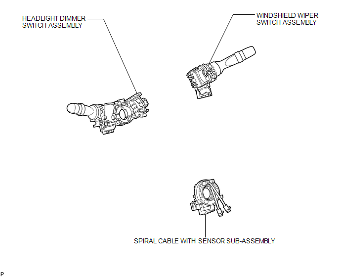
COMPONENTS
ILLUSTRATION
Removal
REMOVAL
PROCEDURE
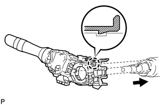
1. REMOVE SPIRAL CABLE WITH SENSOR SUB-ASSEMBLY
(See page .gif) )
)
2. REMOVE WINDSHIELD WIPER SWITCH ASSEMBLY
3. REMOVE HEADLIGHT DIMMER SWITCH ASSEMBLY
|
(a) Disconnect the connector. |
|
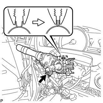
(b) Disengage the clamp as shown in the illustration.
|
(c) Disengage the claw and remove the headlight dimmer switch assembly as shown in the illustration. |
|
Inspection
INSPECTION
PROCEDURE
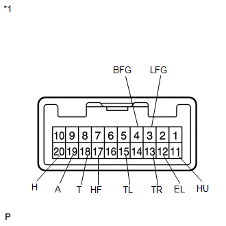
1. INSPECT HEADLIGHT DIMMER SWITCH ASSEMBLY
|
(a) Measure the resistance according to the value(s) in the table below. Standard Resistance: Light Control Switch
If the result is not as specified, replace the headlight dimmer switch assembly. |
|
Installation
INSTALLATION
PROCEDURE
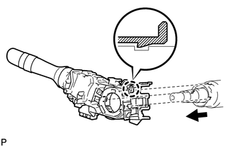
1. INSTALL HEADLIGHT DIMMER SWITCH ASSEMBLY
|
(a) Install the headlight dimmer switch assembly as shown in the illustration. |
|
(b) Engage the claw.
|
(c) Install the headlight dimmer switch assembly with the clamp. |
|

(d) Connect the connector.
2. INSTALL WINDSHIELD WIPER SWITCH ASSEMBLY
.gif)
3. INSTALL SPIRAL CABLE WITH SENSOR SUB-ASSEMBLY
(See page )
 Installation
INSTALLATION
PROCEDURE
1. INSTALL HEADLIGHT ASSEMBLY
(a) Connect each connector.
(b) Install the headlight assembly with the bolt and 3 screws.
Torque:
3.6 N·m {37 kgf·cm, 32 in·lbf}
2. INS ...
 Headlight Leveling Ecu
Components
COMPONENTS
ILLUSTRATION
Removal
REMOVAL
PROCEDURE
1. REMOVE HEADLIGHT LEVELING ECU ASSEMBLY
(a) Disconnect the connector.
...
Other materials about Toyota Venza:
Removal
REMOVAL
PROCEDURE
1. REMOVE AUTOMATIC TRANSAXLE ASSEMBLY
HINT:
See the steps from "Remove Engine Assembly with transaxle" through "Remove Automatic
Transaxle Assembly" (See page ).
2. REMOVE AUTOMATIC TRANSAXLE OIL PAN SUB-ASSEMBLY
...
Wireless Door Lock Buzzer
Components
COMPONENTS
ILLUSTRATION
Installation
INSTALLATION
PROCEDURE
1. INSTALL WIRELESS DOOR LOCK BUZZER
(a) Engage the clamp and install the wireless door lock buzzer.
(b) Connect the ...
Installation
INSTALLATION
PROCEDURE
1. INSTALL POWER STEERING ECU ASSEMBLY
(a) Engage the 4 wire harness clamps to the power steering ECU assembly.
(b) Install the power steering ECU assembly with the ...

0.1341