Toyota Venza: GPS Mark is not Displayed
PROCEDURE
|
1. |
CHECK CABIN |
(a) Check the cabin for any object that might interrupt radio reception or additional devices which use radio waves on the instrument panel. If such an object exists, remove it and check if the GPS mark reappears.
HINT:
The GPS uses extremely faint radio waves originating from satellites. If the signal is interrupted by obstructions or other radio waves, the GPS may not be able to properly receive the signal.
OK:
The GPS mark appears.
| OK | .gif) |
END |
|
.gif)
|
2. |
CHECK SURROUNDINGS |
(a) Check if the vehicle is in a location where GPS signal reception is poor. If the vehicle is in such a place, relocate the vehicle and check if the GPS mark reappears.
HINT:
The GPS uses 24 satellites in 6 orbits. At any point in time, 4 satellites should be able to pinpoint your vehicle. However, GPS signals may not reach the vehicle due to influence from the surroundings, vehicle direction and time. For examples, see the following illustration.
.png) Text in Illustration
Text in Illustration
|
*a |
Example |
*b |
In a tunnel |
|
*c |
In a building |
*d |
Under an overpass |
|
*e |
On a forest or tree-lined path |
*f |
Between tall buildings |
|
*g |
Under a cliff or overhang |
- |
- |
OK:
The GPS mark is displayed.
| OK | |
END (SYSTEM RETURNS TO NORMAL) |
|
|
3. |
CHECK SYSTEM SENSORS (OPERATION CHECK) |
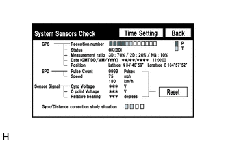
(a) Enter the "System Sensors Check" screen.
Refer to Check System Sensors in Operation Check (See page
.gif) ).
).
(b) Check how many of the following codes appear in the "Reception number".
HINT:
T or P appears.
OK:
At least 3 codes appear.
| OK | |
REPLACE NAVIGATION RECEIVER ASSEMBLY |
| NG | |
PROCEED TO NEXT SUSPECTED AREA SHOWN IN PROBLEM SYMPTOMS TABLE |
 Poor Sound Quality in All Modes (Low Volume)
PROCEDURE
1.
CHECK AUDIO SETTINGS
(a) Set treble, middle and bass to the initial values and check that the sound
is normal.
OK:
The sound returns to normal.
HIN ...
 Route cannot be Calculated
PROCEDURE
1.
SET DESTINATION
(a) Set another destination and check if the system can calculate the route correctly.
OK:
Route can be correctly calculated.
...
Other materials about Toyota Venza:
Reassembly
REASSEMBLY
PROCEDURE
1. INSTALL SHIFT SOLENOID VALVE SL4
(a) Coat the shift solenoid valve SL4 and bolt with ATF.
Text in Illustration
*1
Lock Plate
*2
Solenoid V ...
Inner Rear View Mirror Power Source Circuit
DESCRIPTION
This circuit detects the state of the ignition switch, and sends it to the inner
rear view mirror assembly.
WIRING DIAGRAM
CAUTION / NOTICE / HINT
NOTICE:
Inspect the fuses for circuits related to this system before performing the followin ...
Installation
INSTALLATION
PROCEDURE
1. INSTALL FRONT DOOR OUTSIDE HANDLE ASSEMBLY
(a) Insert the front end of the front door outside handle assembly into
the front door outside handle frame.
(b) Insert the r ...

0.1405