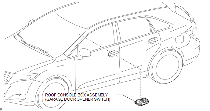
Toyota Venza: Garage Door Opener Switch
Components
COMPONENTS
ILLUSTRATION
Removal
REMOVAL
PROCEDURE
1. REMOVE ROOF CONSOLE BOX ASSEMBLY (GARAGE DOOR OPENER SWITCH)
|
(a) Using a moulding remover, disengage the 2 claws and 2 clips. Text in Illustration
|
|
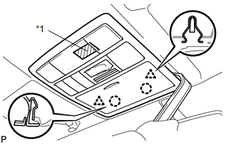
(b) Disengage the fastener and remove the roof console box assembly (garage door opener switch).
Installation
INSTALLATION
PROCEDURE
1. INSTALL ROOF CONSOLE BOX ASSEMBLY (GARAGE DOOR OPENER SWITCH)
|
(a) Engage the fastener. Text in Illustration
|
|
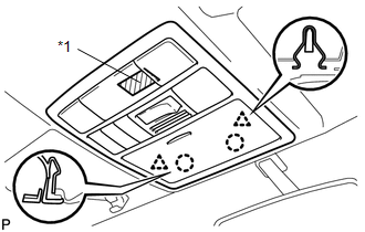
(b) Engage the 2 claws and 2 clips, and install the roof console box assembly (garage door opener switch).


Other materials about Toyota Venza:
Inspection
INSPECTION
PROCEDURE
1. INSPECT INNER REAR VIEW MIRROR ASSEMBLY
(a) Inspect operation of the electrochromic inner mirror.
(1) Connect a positive (+) lead from the battery to terminal 1 and a negative
(-) lead to terminal 2.
(2) Press the AUTO switch.
...
On-vehicle Inspection
ON-VEHICLE INSPECTION
PROCEDURE
1. INSPECT COOLER CONDENSER ASSEMBLY
(a) If the cooler condenser assembly fins are dirty, clean them with water and
dry with compressed air.
NOTICE:
Do not damage the cooler condenser assembly fins.
(b) If any cooler con ...
Transmitter Battery(w/ Smart Key System)
Replacement
REPLACEMENT
PROCEDURE
1. REMOVE TRANSMITTER BATTERY
NOTICE:
Take extra care when handling these precision electronic components.
(a) Push the release hook knob and extract the mechanical key.
...

0.17