Toyota Venza: Rear Sensor Communication Malfunction (C1AED)
DESCRIPTION
This DTC is stored when there is an open or short circuit in the communication line between the rear sensors and the ECU, or when there is a malfunction in a rear sensor.
|
DTC No. |
DTC Detection Condition |
Trouble Area |
|---|---|---|
|
C1AED |
An open or short circuit in the communication line between the rear sensors and ECU or a malfunction in a rear sensor during initialization mode after the engine switch is turned on (IG). |
|
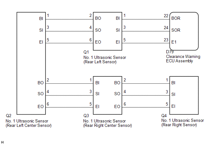
WIRING DIAGRAM
PROCEDURE
|
1. |
CHECK DTC OUTPUT (C1AED) |
(a) Check for DTCs (See page .gif) ).
).
(b) Clear the DTCs (See page ).
(c) Recheck for DTCs (See page ).
|
Result |
Proceed to |
|---|---|
|
DTC C1AED is output |
A |
|
No DTCs are output |
B |
| B | .gif) |
USE SIMULATION METHOD TO CHECK |
|
.gif)
|
2. |
CHECK HARNESS AND CONNECTOR (CLEARANCE WARNING ECU ASSEMBLY - REAR LEFT SENSOR) |
(a) Disconnect the D79 clearance warning ECU assembly connector.
(b) Disconnect the Q1 No. 1 ultrasonic sensor connector.
(c) Measure the resistance according to the value(s) in the table below.
Standard Resistance:
|
Tester Connection |
Condition |
Specified Condition |
|---|---|---|
|
D79-22 (BOR) - Q1-1 (BI) |
Always |
Below 1 Ω |
|
D79-24 (SOR) - Q1-3 (SI) |
Always |
Below 1 Ω |
|
D79-23 (E1) - Q1-5 (EI) |
Always |
Below 1 Ω |
|
D79-22 (BOR) - Body ground |
Always |
10 kΩ or higher |
|
D79-24 (SOR) - Body ground |
Always |
10 kΩ or higher |
|
D79-23 (E1) - Body ground |
Always |
10 kΩ or higher |
| NG | |
REPAIR OR REPLACE HARNESS OR CONNECTOR |
|
|
3. |
CHECK HARNESS AND CONNECTOR (REAR LEFT SENSOR - REAR LEFT CENTER SENSOR) |
(a) Disconnect the Q2 No. 1 ultrasonic sensor connector.
(b) Measure the resistance according to the value(s) in the table below.
Standard Resistance:
|
Tester Connection |
Condition |
Specified Condition |
|---|---|---|
|
Q1-2 (BO) - Q2-1 (BI) |
Always |
Below 1 Ω |
|
Q1-4 (SO) - Q2-3 (SI) |
Always |
Below 1 Ω |
|
Q1-6 (EO) - Q2-5 (EI) |
Always |
Below 1 Ω |
|
Q1-2 (BO) - Body ground |
Always |
10 kΩ or higher |
|
Q1-4 (SO) - Body ground |
Always |
10 kΩ or higher |
|
Q1-6 (EO) - Body ground |
Always |
10 kΩ or higher |
| NG | |
REPAIR OR REPLACE HARNESS OR CONNECTOR |
|
|
4. |
CHECK HARNESS AND CONNECTOR (REAR LEFT CENTER SENSOR - REAR RIGHT CENTER SENSOR) |
(a) Disconnect the Q3 No. 1 ultrasonic sensor connector.
(b) Measure the resistance according to the value(s) in the table below.
Standard Resistance:
|
Tester Connection |
Condition |
Specified Condition |
|---|---|---|
|
Q2-2 (BO) - Q3-1 (BI) |
Always |
Below 1 Ω |
|
Q2-4 (SO) - Q3-3 (SI) |
Always |
Below 1 Ω |
|
Q2-6 (EO) - Q3-5 (EI) |
Always |
Below 1 Ω |
|
Q2-2 (BO) - Body ground |
Always |
10 kΩ or higher |
|
Q2-4 (SO) - Body ground |
Always |
10 kΩ or higher |
|
Q2-6 (EO) - Body ground |
Always |
10 kΩ or higher |
| NG | |
REPAIR OR REPLACE HARNESS OR CONNECTOR |
|
|
5. |
CHECK HARNESS AND CONNECTOR (REAR RIGHT CENTER SENSOR - REAR RIGHT SENSOR) |
(a) Disconnect the Q4 No. 1 ultrasonic sensor connector.
(b) Measure the resistance according to the value(s) in the table below.
Standard Resistance:
|
Tester Connection |
Condition |
Specified Condition |
|---|---|---|
|
Q3-2 (BO) - Q4-1 (BI) |
Always |
Below 1 Ω |
|
Q3-4 (SO) - Q4-3 (SI) |
Always |
Below 1 Ω |
|
Q3-6 (EO) - Q4-5 (EI) |
Always |
Below 1 Ω |
|
Q3-2 (BO) - Body ground |
Always |
10 kΩ or higher |
|
Q3-4 (SO) - Body ground |
Always |
10 kΩ or higher |
|
Q3-6 (EO) - Body ground |
Always |
10 kΩ or higher |
| NG | |
REPAIR OR REPLACE HARNESS OR CONNECTOR |
|
|
6. |
INSPECT NO. 1 ULTRASONIC SENSOR (REAR LEFT SENSOR) |
|
(a) Measure the resistance according to the value(s) in the table below. Standard Resistance:
|
|
.png)
| NG | |
REPLACE NO. 1 ULTRASONIC SENSOR (REAR LEFT SENSOR) |
|
|
7. |
INSPECT NO. 1 ULTRASONIC SENSOR (REAR LEFT CENTER SENSOR) |
|
(a) Measure the resistance according to the value(s) in the table below. Standard Resistance:
|
|
| NG | |
REPLACE NO. 1 ULTRASONIC SENSOR (REAR LEFT CENTER SENSOR) |
|
|
8. |
INSPECT NO. 1 ULTRASONIC SENSOR (REAR RIGHT CENTER SENSOR) |
|
(a) Measure the resistance according to the value(s) in the table below. Standard Resistance:
|
|
| NG | |
REPLACE NO. 1 ULTRASONIC SENSOR (REAR RIGHT CENTER SENSOR) |
|
|
9. |
REPLACE NO. 1 ULTRASONIC SENSOR (REAR LEFT SENSOR) |
|
|
10. |
CHECK DTC OUTPUT (C1AED) |
(a) Clear the DTCs (See page ).
(b) Check for DTCs (See page ).
|
Result |
Proceed to |
|---|---|
|
DTC C1AED is output |
A |
|
No DTCs are output |
B |
| B | |
END |
|
|
11. |
REPLACE NO. 1 ULTRASONIC SENSOR (REAR LEFT CENTER SENSOR) |
|
|
12. |
CHECK DTC OUTPUT (C1AED) |
(a) Clear the DTCs (See page ).
(b) Check for DTCs (See page ).
|
Result |
Proceed to |
|---|---|
|
DTC C1AED is output |
A |
|
No DTCs are output |
B |
| B | |
END |
|
|
13. |
REPLACE NO. 1 ULTRASONIC SENSOR (REAR RIGHT CENTER SENSOR) |
|
|
14. |
CHECK DTC OUTPUT (C1AED) |
(a) Clear the DTCs (See page ).
(b) Check for DTCs (See page ).
|
Result |
Proceed to |
|---|---|
|
DTC C1AED is output |
A |
|
No DTCs are output |
B |
| B | |
END |
|
|
15. |
REPLACE NO. 1 ULTRASONIC SENSOR (REAR RIGHT SENSOR) |
|
|
16. |
CHECK DTC OUTPUT (C1AED) |
(a) Clear the DTCs (See page ).
(b) Check for DTCs (See page ).
|
Result |
Proceed to |
|---|---|
|
DTC C1AED is output |
A |
|
No DTCs are output |
B |
| A | |
REPLACE CLEARANCE WARNING ECU ASSEMBLY |
| B | |
END |
 Front Sensor Communication Malfunction (C1AEC)
DESCRIPTION
This DTC is stored when there is an open or short circuit in the communication
line between the front sensors and the ECU, or when there is a malfunction in a
front sensor.
...
 Rear Right Sensor Malfunction (C1AE9)
DESCRIPTION
The No. 1 ultrasonic sensor (rear right sensor) is installed on the rear bumper.
The ECU detects obstacles based on signals received from the No. 1 ultrasonic sensor
(rear right senso ...
Other materials about Toyota Venza:
Satellite Radio Broadcast cannot be Selected or After Selecting Broadcast, Broadcast
cannot be Added into Memory
CAUTION / NOTICE / HINT
NOTICE:
Some satellite radio broadcasts require payment. A contract must be made between
a satellite radio company and the user. If the contract expires, it will not be
possible to listen to the broadcast.
PROCEDURE
1 ...
Terminals Of Ecu
TERMINALS OF ECU
1. CHECK MAIN BODY ECU (DRIVER SIDE JUNCTION BLOCK ASSEMBLY)
(a) Disconnect the main body ECU (driver side junction block assembly) connectors.
(b) Measure the resistance and voltage according to the value(s) in the table
below.
...
Reassembly
REASSEMBLY
CAUTION / NOTICE / HINT
NOTICE:
Before installation, apply high temperature grease to the parts indicated by
arrows (See page ).
PROCEDURE
1. INSTALL NO. 2 PARKING BRAKE SHOE HOLD DOWN SPRING PIN (for 2WD)
(a) Install the No. 2 p ...

0.1913