Toyota Venza: Front Axle Hub Bolt
Components
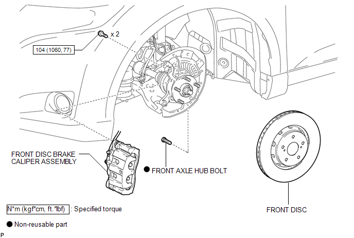
COMPONENTS
ILLUSTRATION
Replacement
REPLACEMENT
CAUTION / NOTICE / HINT
HINT:
- Use the same procedure for the RH side and LH side.
- The procedure listed below is for the LH side.
PROCEDURE
1. REMOVE FRONT WHEEL
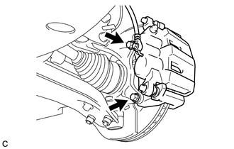
2. SEPARATE FRONT DISC BRAKE CALIPER ASSEMBLY
|
(a) Remove the 2 bolts and separate the front disc brake caliper assembly. NOTICE: Use wire or an equivalent tool to keep the front disc brake caliper assembly from hanging down by the flexible hose. |
|
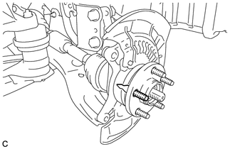
3. REMOVE FRONT DISC
.gif)
4. REMOVE FRONT AXLE HUB BOLT
|
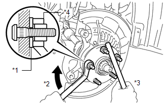
(a) Position the front axle hub bolt to be removed as shown in the illustration. |
|
|
(b) Temporarily install the 2 nuts to the front axle hub bolt as shown in the illustration. Recommended service nut: Thread diameter: 12.0 mm (0.472 in.) Thread pitch: 1.5 mm (0.0591 in.) NOTICE: Install the nuts to prevent damage to the front axle hub bolts. |
|
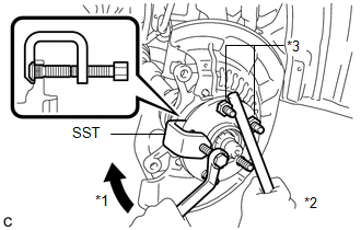
(c) Using SST and a brass bar or an equivalent tool to hold the front axle hub, remove the front axle hub bolt.
SST: 09628-10011
Text in Illustration|
*1 |
Turn |
|
*2 |
Hold |
|
*3 |
Nut |
5. INSTALL FRONT AXLE HUB BOLT
|
(a) Position a new front axle hub bolt to be installed as shown in the illustration. |
|
|
(b) Temporarily install the new front axle hub bolt to the front axle hub. |
|
(c) Install a washer and nut to the new front axle hub bolt as shown in the illustration.
Recommended service nut:
Thread diameter: 12.0 mm (0.472 in.)
Thread pitch: 1.5 mm (0.0591 in.)
HINT:
The thickness of the washer is preferably 5 mm (0.197 in.) or more.
(d) Using a brass bar or an equivalent tool to hold the front axle hub, install the front axle hub bolt by tightening the nut.
Text in Illustration|
*1 |
Washer |
|
*2 |
Turn |
|
*3 |
Hold |
|
*4 |
Nut |
NOTICE:
- Install the nuts to prevent damage to the front axle hub bolts.
- Do not damage the threads of the front axle hub bolts.
(e) Remove the 3 nuts and washer from the 3 front axle hub bolts.
6. INSTALL FRONT DISC
7. INSTALL FRONT DISC BRAKE CALIPER ASSEMBLY
|
(a) Install the front disc brake caliper assembly to the steering knuckle with the 2 bolts. Torque: 104 N·m {1060 kgf·cm, 77 ft·lbf} NOTICE: Do not twist the brake hose when installing the front disc brake caliper assembly. |
|
8. INSTALL FRONT WHEEL
Torque:
103 N·m {1050 kgf·cm, 76 ft·lbf}
 Installation
INSTALLATION
CAUTION / NOTICE / HINT
HINT:
Use the same procedure for the RH side and LH side.
The procedure listed below is for the LH side.
PROCEDURE
1. INSTALL FRONT AXLE HUB ...

Other materials about Toyota Venza:
Installation
INSTALLATION
PROCEDURE
1. INSTALL OUTER MIRROR SWITCH
(a) Engage the 4 claws to install the outer mirror switch.
2. INSTALL OUTER MIRROR SWITCH ASSEMBLY
(a) Engage the 2 claws to install ...
System Diagram
SYSTEM DIAGRAM
Communication Table
Transmitting ECU
Receiving ECU
Signal
Communication Method
Air Conditioning Control Assembly
Air Conditioning Amplifier Assembly
Rear windo ...
Removal
REMOVAL
PROCEDURE
1. REMOVE REAR SEAT HEADREST ASSEMBLY
2. REMOVE REAR SEAT CENTER HEADREST ASSEMBLY
3. REMOVE REAR SEAT INNER TRACK BRACKET COVER
4. REMOVE REAR SEAT OUTER TRACK BRACKET COVER
5. DISCONNECT REAR SEAT RECLINING CONTROL CABLE S ...

0.1717