Toyota Venza: Back Door Lock
Components
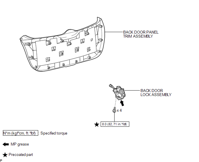
COMPONENTS
ILLUSTRATION
Removal
REMOVAL
PROCEDURE
1. REMOVE BACK DOOR PANEL TRIM ASSEMBLY
.gif)
2. REMOVE BACK DOOR LOCK ASSEMBLY
|
(a) Disconnect the connector. |
|
.png)
(b) Disengage the clamp.
(c) Remove the bolt.
|
(d) Remove the 3 bolts and back door lock assembly. |
|
.png)
Inspection
INSPECTION
PROCEDURE
1. INSPECT BACK DOOR LOCK ASSEMBLY
(a) Check the operation of the door lock motor.
.png)
(1) Apply the battery voltage to the door lock motor and check the operation of the door lock motor.
OK:
|
Measurement Condition |
Specified Condition |
|---|---|
|
Battery positive (+) → Terminal 1 (M+) Battery negative (-) → Terminal 2 (M-) |
Latch turns to full-latch position |
|
Battery positive (+) → Terminal 2 (M-) Battery negative (-) → Terminal 1 (M+) |
Latch turns to open-latch position |
If the result is not specified, replace the back door lock.
(b) Check the operation of the switch.
(1) Measure the resistance according to the value(s) in the table below.
Standard Resistance:
Latch Switch
|
Tester Connection |
Door Lock Latch Position |
Specified Condition |
|---|---|---|
|
5 (ULSW) - 4 (E) |
Open-latch |
Below 1 Ω |
|
5 (ULSW) - 4 (E) |
Half-latch |
10 kΩ or higher |
|
5 (ULSW) - 4 (E) |
Full-latch |
10 kΩ or higher |
|
5 (ULSW) - 4 (E) |
Over-latch |
Below 1 Ω |
Sector Switch
|
Tester Connection |
Condition |
Specified Condition |
|---|---|---|
|
6 (DLSW) - 4 (E) |
Sector gear in neutral position (Sector switch on) |
Below 1 Ω |
|
6 (DLSW) - 4 (E) |
Sector gear not in neutral position (Sector switch off) |
10 kΩ or higher |
Back Door Courtesy Light Switch
|
Tester Connection |
Door Lock Latch Position |
Specified Condition |
|---|---|---|
|
3 (CTY) - 4 (E) |
Open-latch |
Below 1 Ω |
|
3 (CTY) - 4 (E) |
Half-latch |
Below 1 Ω |
|
3 (CTY) - 4 (E) |
Full-latch |
10 kΩ or higher |
|
3 (CTY) - 4 (E) |
Over-latch |
10 kΩ or higher |
If the result is not specified, replace the back door lock assembly.
Installation
INSTALLATION
PROCEDURE
1. INSTALL BACK DOOR LOCK ASSEMBLY
(a) Apply MP grease to the sliding parts of the back door lock assembly.
(b) Apply adhesive to the threads of the bolt.
Adhesive:
Toyota Genuine Adhesive 1324, Three Bond 1324 or equivalent
|
(c) Install the back door lock assembly with the 3 bolts. Torque: 8.0 N·m {82 kgf·cm, 71 in·lbf} |
|
.png)
|
(d) Install the bolt. Torque: 8.0 N·m {82 kgf·cm, 71 in·lbf} |
|
.png)
(e) Engage the clamp.
(f) Connect the connector.
2. INSTALL BACK DOOR PANEL TRIM ASSEMBLY
.gif)
 Door Lock
...

Other materials about Toyota Venza:
Installation
INSTALLATION
PROCEDURE
1. INSTALL FUEL PRESSURE PULSATION DAMPER ASSEMBLY
(a) Apply a light coat of gasoline or spindle oil to a new O-ring.
Text in Illustration
*1
O-ring
...
VSC OFF Indicator Light Remains ON
DESCRIPTION
The skid control ECU is connected to the combination meter via CAN communication.
Pressing the VSC OFF switch turns off traction control and pressing and holding
this switch turns off traction and VSC controls. If VSC control is turned off, the ...
Steering wheel
The steering wheel can be adjusted to a comfortable position.
Hold the steering wheel and press the lever down.
Adjust to the ideal position by moving the steering wheel horizontally and vertically.
After adjustment, pull the lever up to secure the stee ...

0.1866