Toyota Venza: Electrical Key Oscillator(for Rear Side)
Components
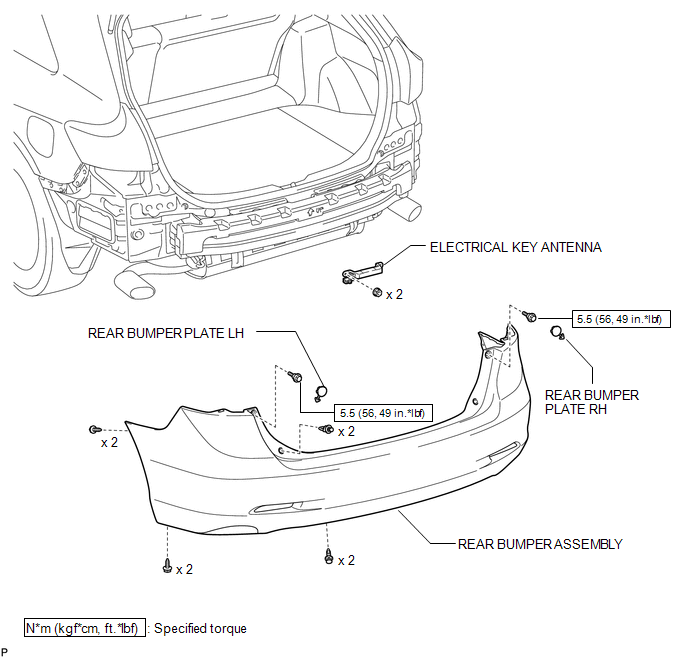
COMPONENTS
ILLUSTRATION
Removal
REMOVAL
PROCEDURE
1. REMOVE REAR BUMPER PLATE LH
.gif)
2. REMOVE REAR BUMPER PLATE RH
3. REMOVE REAR BUMPER ASSEMBLY
4. REMOVE ELECTRICAL KEY ANTENNA
|
(a) Disconnect the connector. |
|
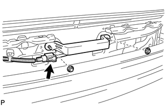
(b) Remove the 2 nuts and the electrical key antenna.
NOTICE:
Be careful when removing the electrical key antenna. If the antenna is dropped, replace it with a new one.
Installation
INSTALLATION
PROCEDURE
1. INSTALL ELECTRICAL KEY ANTENNA
|
(a) Install the electrical key antenna with the 2 nuts. NOTICE: Be careful when installing the electrical key antenna. If the antenna is dropped, replace it with a new one. |
|
.png)
(b) Connect the connector.
2. INSTALL REAR BUMPER ASSEMBLY
.gif)
3. INSTALL REAR BUMPER PLATE LH
4. INSTALL REAR BUMPER PLATE RH
 Electrical Key Oscillator(for Rear Floor)
Components
COMPONENTS
ILLUSTRATION
Removal
REMOVAL
PROCEDURE
1. REMOVE TONNEAU COVER ASSEMBLY (w/ Tonneau Cover)
2. REMOVE DECK BOARD ASSEMBLY
3. REMOVE NO. 3 DECK BOARD SUB-ASSEMB ...
 Engine Hood Courtesy Switch
Components
COMPONENTS
ILLUSTRATION
Inspection
INSPECTION
PROCEDURE
1. INSPECT SECURITY COURTESY SWITCH (HOOD LOCK ASSEMBLY)
(a) Measure the resistance according to the value(s) ...
Other materials about Toyota Venza:
Problem Symptoms Table
PROBLEM SYMPTOMS TABLE
HINT:
Use the table below to help determine the cause of problem symptoms.
If multiple suspected areas are listed, the potential causes of the symptoms
are listed in order of probability in the "Suspected Area" ...
Engine compartment
► 2GR-FE engine
1. Engine coolant reservoir
2. Engine oil filler cap
3. Engine oil level dipstick
4. Brake fluid reservoir
5. Battery
6. Fuse box
7. Electric cooling fans
8. Condenser
9. Radiator
10.Washer fluid tank
► 1AR-FE engine
...
Installation
INSTALLATION
PROCEDURE
1. ADJUST COMPRESSOR OIL LEVEL
(a) When replacing the cooler compressor assembly with a new one, gradually
discharge the inert gas (helium) from the service valve, and drain the following
amount of oil from the vent ...

0.1271