Toyota Venza: Electrical Key Oscillator(for Rear Floor)
Components
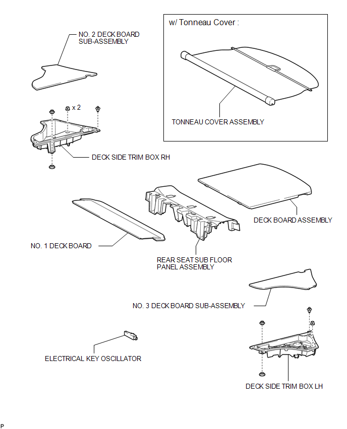
COMPONENTS
ILLUSTRATION
Removal
REMOVAL
PROCEDURE
1. REMOVE TONNEAU COVER ASSEMBLY (w/ Tonneau Cover)
.gif)
2. REMOVE DECK BOARD ASSEMBLY
3. REMOVE NO. 3 DECK BOARD SUB-ASSEMBLY
4. REMOVE DECK SIDE TRIM BOX LH
5. REMOVE NO. 2 DECK BOARD SUB-ASSEMBLY
6. REMOVE DECK SIDE TRIM BOX RH
7. REMOVE NO. 1 DECK BOARD
8. REMOVE REAR SEAT SUB FLOOR PANEL ASSEMBLY
9. REMOVE ELECTRICAL KEY OSCILLATOR
|
(a) Disconnect the connector. |
|
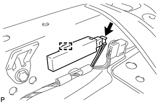
(b) Disengage the clamp and remove the electrical key oscillator.
NOTICE:
Be careful when removing the electrical key oscillator. If the oscillator is dropped, replace it with a new one.
Installation
INSTALLATION
PROCEDURE
1. INSTALL ELECTRICAL KEY OSCILLATOR
|
(a) Engage the clamp and install the electrical key oscillator. NOTICE: Be careful when installing the electrical key oscillator. If the oscillator is dropped, replace it with a new one. |
|
.png)
(b) Connect the connector.
2. INSTALL REAR SEAT SUB FLOOR PANEL ASSEMBLY
.gif)
3. INSTALL NO. 1 DECK BOARD
4. INSTALL DECK SIDE TRIM BOX RH
5. INSTALL NO. 2 DECK BOARD SUB-ASSEMBLY
6. INSTALL DECK SIDE TRIM BOX LH
7. INSTALL NO. 3 DECK BOARD SUB-ASSEMBLY
8. INSTALL DECK BOARD ASSEMBLY
9. INSTALL TONNEAU COVER ASSEMBLY (w/ Tonneau Cover)
 Electrical Key Oscillator(for Front Floor)
Components
COMPONENTS
ILLUSTRATION
Installation
INSTALLATION
PROCEDURE
1. INSTALL ELECTRICAL KEY OSCILLATOR
(a) Engage the clamp and install the electrical key oscillator.
N ...
 Electrical Key Oscillator(for Rear Side)
Components
COMPONENTS
ILLUSTRATION
Removal
REMOVAL
PROCEDURE
1. REMOVE REAR BUMPER PLATE LH
2. REMOVE REAR BUMPER PLATE RH
3. REMOVE REAR BUMPER ASSEMBLY
4. REMOVE ELECTRICAL K ...
Other materials about Toyota Venza:
Installation
INSTALLATION
PROCEDURE
1. INSTALL SHIFT LEVER ASSEMBLY
NOTICE:
Check that the park/neutral position switch and the shift lever are in neutral.
(a) Slide the slider of the transmission control cable in the direction
indicated by the arrow an ...
Power back door switch (vehicles with power back door)
Push the switch to close.
Pressing the switch again while the power back door is closing will cause it
to open again.
However, the reverse operation cannot be performed for the first second after
pressing the switch to close the door.
The back door ca ...
Removal
REMOVAL
CAUTION / NOTICE / HINT
NOTICE:
When disconnecting the steering intermediate shaft assembly and pinion shaft
of the steering gear assembly, be sure to place matchmarks before servicing.
PROCEDURE
1. PLACE FRONT WHEELS FACING STRAIGHT AHEAD
2. S ...

0.143