Toyota Venza: Dtc Check / Clear
DTC CHECK / CLEAR
1. DTC CHECK/CLEAR (USING TECHSTREAM)
(a) CHECK DTC
(1) Connect the Techstream to the DLC3.
(2) Turn the ignition switch on (IG).
(3) Read the DTC by following the prompts on the Techstream screen.
HINT:
Refer to the Techstream operator's manual for further details.
(b) CLEAR DTC
(1) Connect the Techstream to the DLC3.
(2) Turn the ignition switch on (IG).
(3) Clear the DTC by following the directions on the Techstream screen.
HINT:
The Techstream has a SNAPSHOT function which records the monitored data.
Refer to the Techstream operator's manual for further details.
2. SELF-DIAGNOSTIC MODE (OPERATING IGNITION KEY CYLINDER)
(a) Switch to self-diagnostic mode.
(1) Insert the key into the ignition key cylinder and remove it.
(2) Within 5 seconds after the key is removed, insert it into the ignition key cylinder and then turn the ignition switch to ON then off once. (End in off)
(3) Within 30 seconds after turning the ignition switch off, perform the following 9 times: Turn the ignition switch to ON then off. (End in off)
HINT:
Turning the ignition switch to ON after the procedure above has been completed will end the self-diagnostic mode.
NOTICE:
If the system fails to enter self-diagnostic mode, the system will return to normal mode.
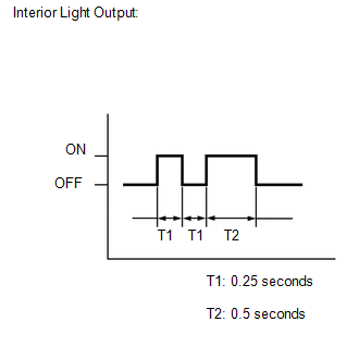
(b) Check that the system has switched to self-diagnostic mode by checking the interior light output pattern.
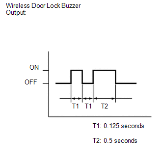
(c) Check that the system has switched to self-diagnostic mode by checking the wireless door lock buzzer output pattern.
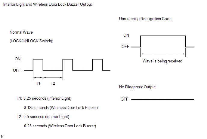
(d) Check the diagnostic outputs when the door control transmitter switch is held down. The diagnostic outputs can be checked by the interior light and wireless door lock buzzer patterns.
3. SELF-DIAGNOSTIC MODE (USING TECHSTREAM)
(a) Switch to self-diagnostic mode.
(1) Connect the Techstream to the DLC3.
(2) Turn the ignition switch to ON and turn the Techstream main switch on.
HINT:
Refer to the Techstream operator's manual for further details.
 Data List / Active Test
DATA LIST / ACTIVE TEST
1. DATA LIST
HINT:
Using the Techstream to read the Data List allows the values or states of switches,
sensors, actuators and other items to be read without removing any p ...
 Diagnostic Trouble Code Chart
DIAGNOSTIC TROUBLE CODE CHART
HINT:
If a trouble code is output during the DTC check, inspect the trouble areas listed
for that code. For details of the code, refer to "See page" in the ...
Other materials about Toyota Venza:
Removal
REMOVAL
PROCEDURE
1. DISCONNECT CABLE FROM NEGATIVE BATTERY TERMINAL
CAUTION:
Wait at least 90 seconds after disconnecting the cable from the negative (-)
battery terminal to disable the SRS system.
NOTICE:
When disconnecting the cable, some systems ne ...
Intake System
Parts Location
PARTS LOCATION
ILLUSTRATION
System Diagram
SYSTEM DIAGRAM
On-vehicle Inspection
ON-VEHICLE INSPECTION
PROCEDURE
1. INSPECT INTAKE SYSTEM
HINT:
Perform "Inspection After Repair" after repairing vacuum leaks in the ...
Power windows
The power windows can be opened and closed using the following switches.
1. One-touch closing*
2. Closing
3. One-touch opening*
4. Opening
*:To stop the window partway, operate the switch in the opposite direction.
Lock switch
Press the switch down ...

0.1787