Toyota Venza: Driver Side Seat Belt Warning Light does not Operate
DESCRIPTION
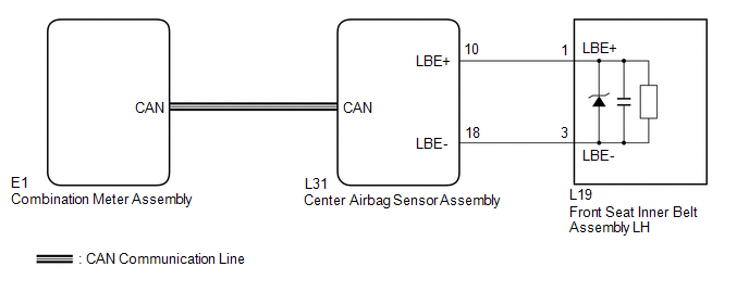
When the ignition switch is ON, the center airbag sensor assembly transmits front seat inner belt status signals to the combination meter assembly through CAN. If the driver seat belt is not fastened, the combination meter assembly blinks the driver side seat belt warning light. If the seat belt is fastened, the warning light goes off.
WIRING DIAGRAM
CAUTION / NOTICE / HINT
NOTICE:
The seat belt warning system uses the CAN communication system. First, confirm
that there is no malfunction in the CAN communication system. Refer to the How to
Proceed with Troubleshooting procedure (See page
.gif) ).
).
PROCEDURE
|
1. |
CHECK DTC OUTPUT (CAN COMMUNICATION SYSTEM) |
(a) Clear the DTC (See page ).
(b) Recheck for DTCs.
|
Result |
Proceed to |
|---|---|
|
DTC is not output |
A |
|
DTC is output |
B |
| B | .gif) |
GO TO CAN COMMUNICATION SYSTEM |
|
.gif)
|
2. |
CHECK DTC OUTPUT (AIRBAG SYSTEM) |
(a) Clear the DTC (See page ).
(b) Recheck for DTCs.
|
Result |
Proceed to |
|---|---|
|
DTC is not output |
A |
|
DTC is output |
B |
| B | |
GO TO AIRBAG SYSTEM |
|
|
3. |
PERFORM ACTIVE TEST USING TECHSTREAM |
(a) Connect the Techstream to the DLC3.
(b) Turn the ignition switch to ON.
(c) Turn the Techstream on.
(d) Enter the following menus: Body Electrical / Combination Meter / Active Test.
(e) Perform the Active Test according to the display on the Techstream.
Combination Meter (Combination Meter Assembly)|
Tester Display |
Test Part |
Control Range |
Diagnostic Note |
|---|---|---|---|
|
Driver Side Seat Belt |
Driver side seat belt warning light |
OFF or ON |
Confirm that the vehicle stopped with the engine idling |
OK:
The driver side seat belt warning light on the combination meter assembly operates normally.
| OK | |
USE SIMULATION METHOD TO CHECK |
| NG | |
REPLACE COMBINATION METER ASSEMBLY |
 Data List / Active Test
DATA LIST / ACTIVE TEST
1. DATA LIST
HINT:
Using the Techstream to read the Data List allows the values or states of switches,
sensors, actuators and other items to be read without removing any p ...
 On-vehicle Inspection
ON-VEHICLE INSPECTION
PROCEDURE
1. INSPECT DRIVER SIDE SEAT BELT WARNING
(a) Turn the ignition switch to ON.
(b) When the driver side seat belt is not fastened, check that the driver side
seat b ...
Other materials about Toyota Venza:
ECU Power Source Circuit
DESCRIPTION
This circuit provides power for main body ECU (driver side junction block assembly)
operation.
WIRING DIAGRAM
PROCEDURE
1.
CHECK DRIVER SIDE JUNCTION BLOCK ASSEMBLY (MAIN BODY ECU (POWER SOURCE))
...
Ambient Temperature Sensor
Components
COMPONENTS
ILLUSTRATION
Inspection
INSPECTION
PROCEDURE
1. INSPECT AMBIENT TEMPERATURE SENSOR
(a) Measure the resistance according to the value(s) in the table below.
Standard Resistance:
Tester Connection
C ...
Relay
On-vehicle Inspection
ON-VEHICLE INSPECTION
PROCEDURE
1. INSPECT DOME CUT RELAY
(a) Measure the resistance according to the value(s) in the table below.
Standard Resistance:
Tester Connection
Condition
...

0.1503